Modified structure of battery integral installation jig

A fixture and battery technology, applied in the direction of lead-acid batteries, lead-acid battery construction, auxiliary devices, etc., can solve the problems of fast wear of fixtures, low service life, time-consuming, etc., to improve work efficiency, improve service life, overall structure compact effect

Active Publication Date: 2010-08-04
ZHEJIANG HAIYUE AUTOMATIC MACHINERY
View PDF0 Cites 6 Cited by
  • Summary
  • Abstract
  • Description
  • Claims
  • Application Information

AI Technical Summary

Problems solved by technology

However, the existing fixture has the following disadvantages: after the welding operation, it is necessary to manually remove the splint to take out the battery cell, so that the welding process consumes a lot of man-

Method used


Image

  • Modified structure of battery integral installation jig
  • Modified structure of battery integral installation jig
  • Modified structure of battery integral installation jig

Examples


Embodiment Construction

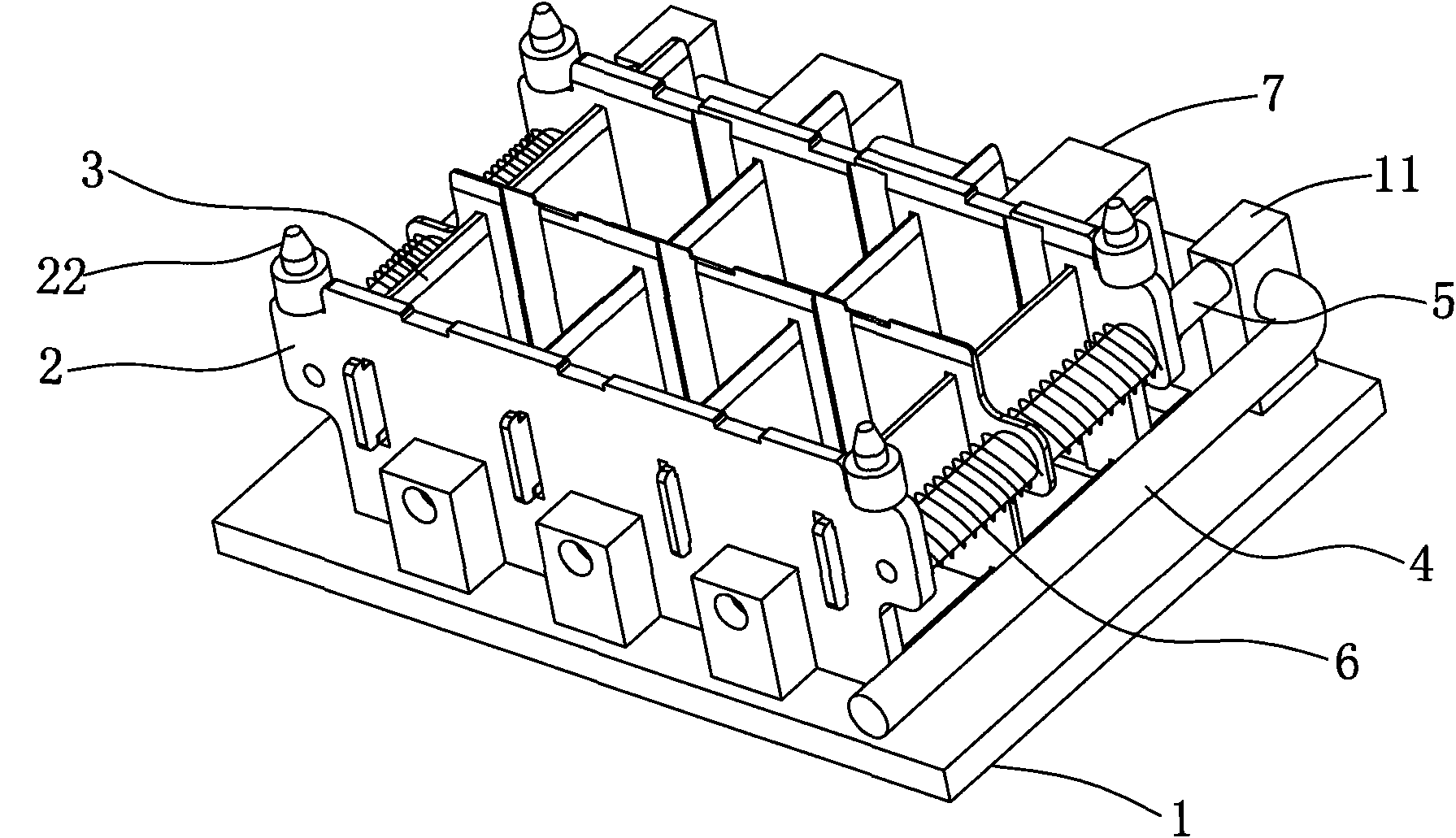
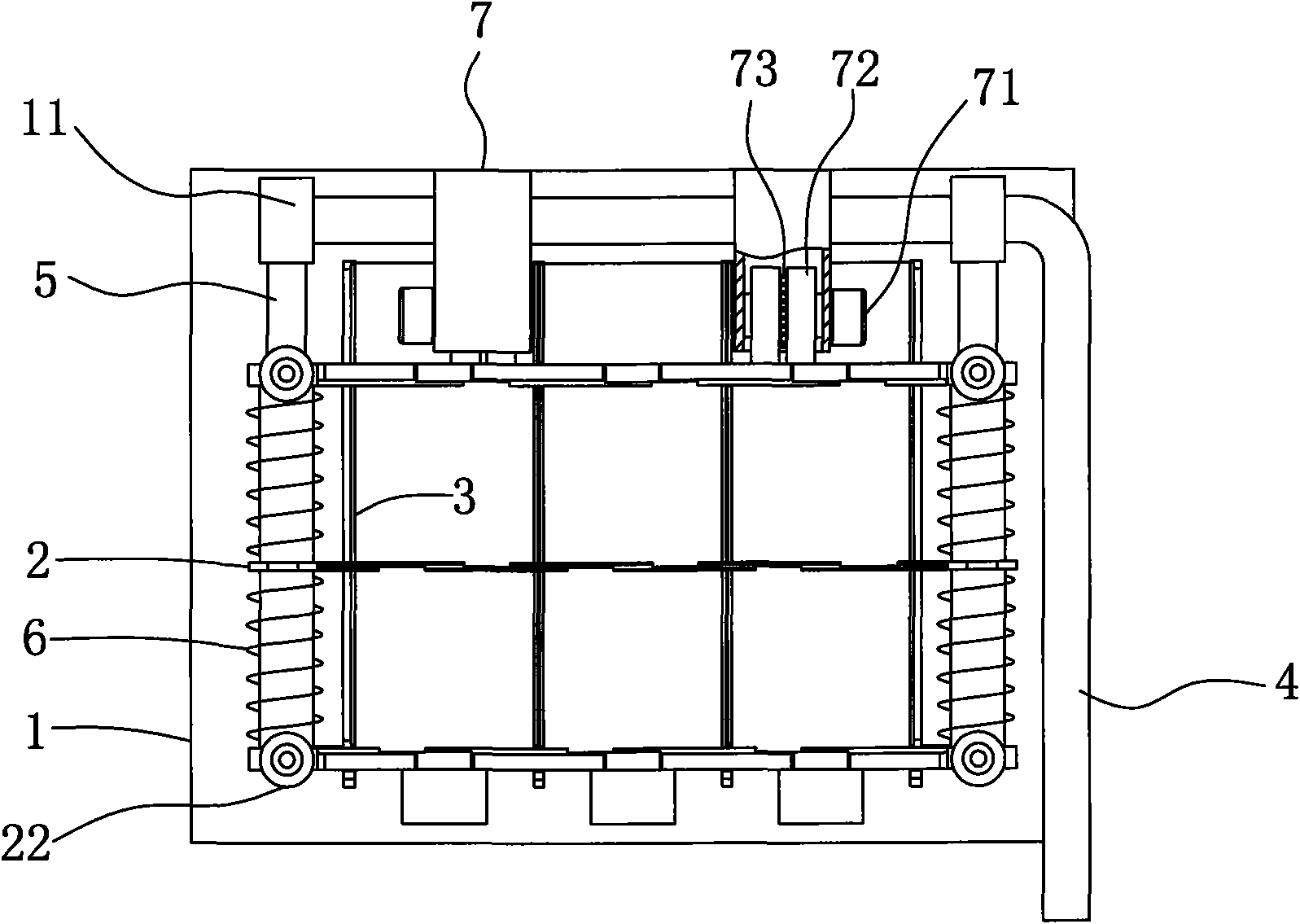
[0017] Such as figure 1 , figure 2 As shown, the present invention is an improved structure of a battery assembly fixture, including a bottom plate 1, on which a movable frame composed of several splints and a clamping mechanism for tightening the movable frame are installed. The tightening mechanism is provided with a rolling chuck acting on the splint. The rolling chuck greatly reduces the friction between the clamping mechanism and the splint, which improves the service life of the clamp.

[0018] The movable frame is composed of several parallel fixed splints 3 and movable splints 2 arranged in a staggered manner. The movable splint 2 is provided with a chute 23, the fixed splint 3 is installed in the chute 23, and the rolling chuck acts on the movable splint. 2 on. The clamping mechanism includes several pads 11 arranged side by side on one side of the base plate 1, the L-shaped handle 4 is flexibly connected to the pads 11, and the L-shaped handle 4 is provided with ...


PUM


Abstract

The invention discloses a modified structure of a battery integral installation jig. The jig comprises a base plate, wherein the base plate is provided with a movable frame composed of a plurality of clamping plates and a clamping mechanism used for tightening up the movable frame, and the clamping mechanism is provided with a rolling chuck to act on the clamping plates. By adopting the rolling chuck, the friction between the clamping mechanism and the clamping plates is greatly reduced, thus increasing the service life of the jig. The overall structure of the invention is compact, the operation is convenient, the reset can be performed without manual operation, the production time is saved, and the work efficiency is increased.

Description

technical field [0001] The invention relates to a welding jig, in particular to an improved structure of a complete jig for welding battery cells. Background technique [0002] At present, lead-acid batteries have been used in many fields such as power generation, lighting, and transportation. They are widely used batteries. There are multiple battery cells inside the lead-acid battery. The negative plates are connected by bus bars. When making battery cells, in order to facilitate welding, it is necessary to fix multiple battery cells in a certain shape with a special fixture, and then weld them. However, the existing fixture has the following disadvantages: after the welding operation, it is necessary to manually remove the splint to take out the battery cell, so that the welding process consumes a lot of man-hours, the labor intensity of the workers is high, and the efficiency is low; the clamping block of the fixture is affected by its own gravity. It is easy to loosen ...

Claims


Application Information

Patent Timeline
IPC IPC(8): B23K37/053H01M10/12
CPCY02E60/126Y02E60/10Y02P70/50
Inventor 陈义忠
Owner ZHEJIANG HAIYUE AUTOMATIC MACHINERY
Why Eureka
Try Eureka