
Anti-electromagnetic field powerful optical cable

A powerful, electromagnetic field technology, applied in the field of communication, can solve the problems of increased transmission loss of optical cable, large electromagnetic signal interference, poor impact resistance, etc., to achieve the effect of increased transmission loss, high lateral pressure resistance, and high impact resistance.

Inactive Publication Date: 2010-08-04
ZHEJIANG ZHONGTIAN WIRE & CABLE
View PDF9 Cites 1 Cited by
  • Summary
  • Abstract
  • Description
  • Claims
  • Application Information

AI Technical Summary

Problems solved by technology

The first structure has the following disadvantages: the optical fiber suffers from hydrogen damage due to the oxidation of the phosphating steel wire or the steel-aluminum strip, resulting in a substantial increase in the transmission loss of the optical cable; it affects the use in the environment of a strong electromagnetic field
The second structure has the following disadvantages: insufficient tensile strength; poor impact resistance
It solves the shortcomings of existing products such as poor tensile resistance and large electromagnetic signal interference, and has the advantages of light weight, high strength, and small interference to electromagnetic signals.
The above scheme improves the performance of the optical cable to a certain extent, but still cannot fundamentally solve the problems of the prior art

Method used


Image

  • Anti-electromagnetic field powerful optical cable
  • Anti-electromagnetic field powerful optical cable

Examples


Embodiment Construction

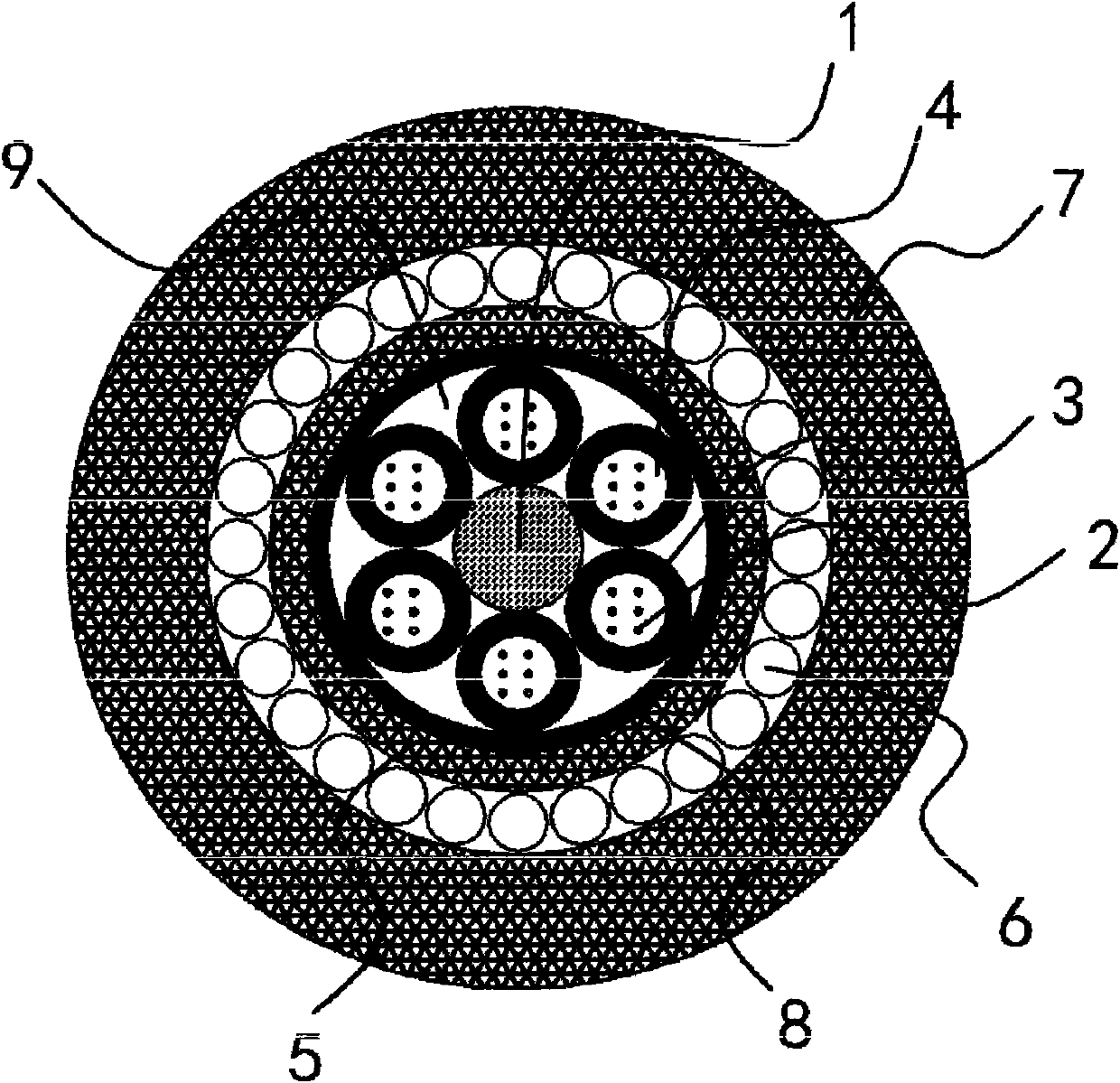
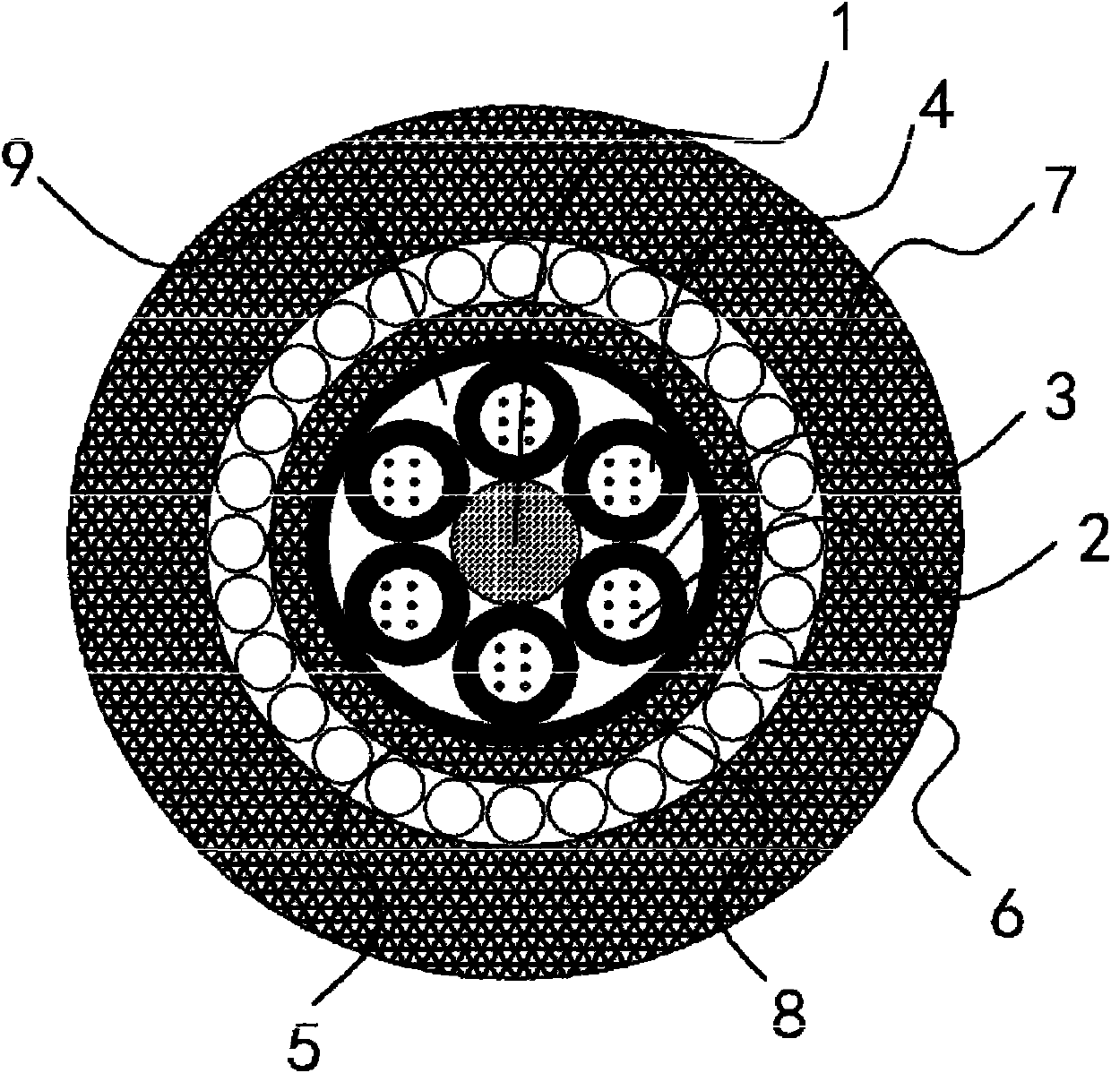
[0016] Such as figure 1 As shown, the anti-electromagnetic field strong optical cable includes a central strength member 1 and several cable cores 2 . The cable core 2 is an all-dielectric fiber bundle or fiber ribbon. The outer periphery of each cable core 2 is respectively covered with a loose tube 3 , and the fiber paste 4 surrounding the cable core 2 is arranged in the loose tube 3 , and the loose tube 3 is stranded around the central reinforcement 1 in a single layer. The outer periphery of the loose tube 3 is provided with a first protective cover 5 that covers each loose tube 3 , and a number of galvanized steel wires 6 wound thereon are arranged on the outer periphery of the first protective cover 5 . A second protective sheath 7 covering each galvanized steel wire 6 is arranged on the periphery.

[0017] In this embodiment, a waterproof layer 8 is also provided between the first protective sheath 5 and the loose tube 3, and the waterproof layer 8 is made of polyeste...


PUM


Abstract

The invention belongs to the technical field of communication, and relates to an anti-electromagnetic field powerful optical cable. The anti-electromagnetic field powerful optical cable solves the technical problems that the prior art has low structural strength, poor performance and the like. The anti-electromagnetic field powerful optical cable comprises a center reinforcer and a plurality of cable cores, wherein a loose bushing is sleeved on the periphery of each cable core respectively; a fiber paste for enclosing and protecting the cable core is arranged in the loose bushing; the loose bushing is intertwisted around the center reinforcer; the periphery of the loose bushing is provided with a first protective cover for covering each loose bushing; the periphery of the first protective cover is provided with a plurality of galvanized steel wires enwound on the first protective cover; and the peripheries of the galvanized steel wires are provided with second protective covers for covering each galvanized steel wire. The anti-electromagnetic field powerful optical cable has the following advantages that: 1, the weatherability is good, the high and low temperature properties are excellent, and optical fibers have no hydrogen losses caused by the oxidation of phosphorized steel wire or steel strips; 2, the tensile strength, lateral pressure resisting intensity and impact resistance are high, metal components are completely isolated from the cable cores, and the optical cable can also be used normally in a strong electromagnetic field environment; and 3, the structure is compact, the production process is simple, and the optical cable can be produced by using existing equipment.

Description

technical field [0001] The invention belongs to the technical field of communication and relates to an optical cable, in particular to an anti-electromagnetic field strong optical cable. Background technique [0002] The traditional optical cable adopts two structures: 1. The central strength member is made of steel wire, and the steel (aluminum)-PE sheath is wrapped outside the cable core; 2. The central strength member is made of glass fiber, and the cable core is wrapped with a PE sheath. The use of the first structure has the following disadvantages: the optical fiber suffers from hydrogen damage due to the oxidation of the phosphating steel wire or the steel-aluminum strip, resulting in a substantial increase in the transmission loss of the optical cable; it affects the use in a strong electromagnetic field environment. The second structure has the following disadvantages: insufficient tensile strength; poor impact resistance. [0003] For this reason, people have carr...

Claims


Application Information

Patent Timeline
Patent Type & Authority Applications(China)
IPC IPC(8): G02B6/44
Inventor 王永明
Owner ZHEJIANG ZHONGTIAN WIRE & CABLE
Learn More