Electric machine and rotor arrangement

A technology for rotors and synchronous motors, applied in electromechanical devices, electrical components, electrical components, etc., to solve problems such as unknown offsets

Inactive Publication Date: 2010-08-04
ROBERT BOSCH GMBH
View PDF0 Cites 16 Cited by
  • Summary
  • Abstract
  • Description
  • Claims
  • Application Information

AI Technical Summary

Problems solved by technology

[0005] However, the arc radius and its offset from the axis, which are optimized for an as sinusoi...

Method used


Image

  • Electric machine and rotor arrangement
  • Electric machine and rotor arrangement
  • Electric machine and rotor arrangement

Examples


Embodiment Construction

[0028] The same reference numerals in the following embodiments represent elements with the same or similar functions.

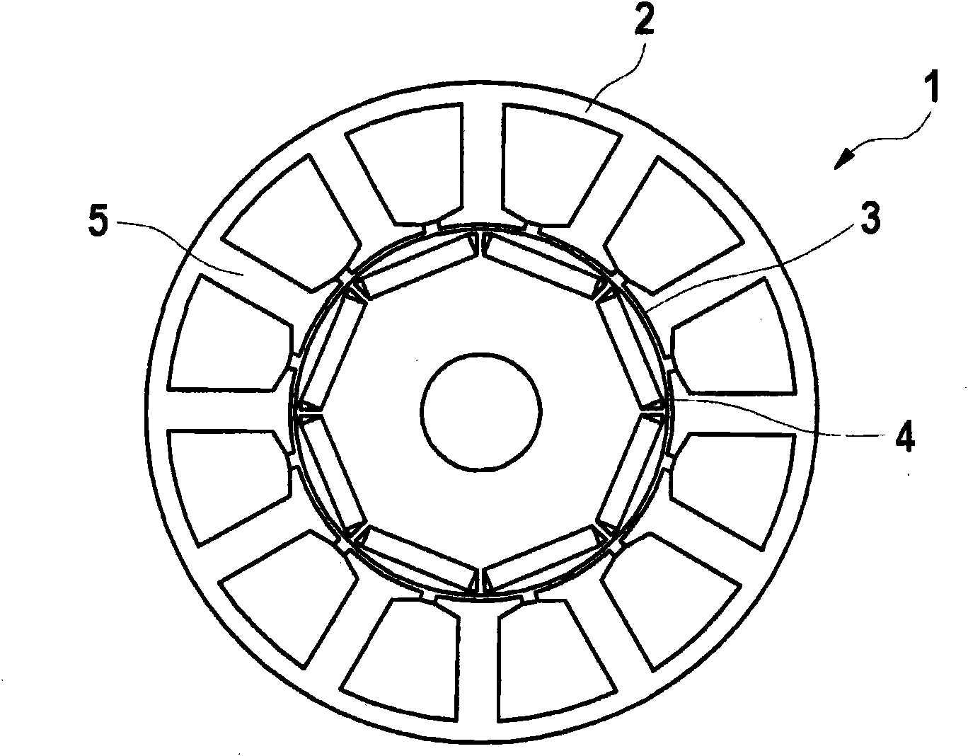
[0029] figure 1 Shown is a schematic cross-sectional view of an electric machine, in particular a permanently excited synchronous machine 1 , with a stator arrangement 2 with a stator interior 3 therein. A rotor device 4 rotatable about an axis is mounted in the stator inner chamber 3 . The stator arrangement 2 has stator teeth 5 pointing towards the rotor arrangement 4 (inwardly), all or part of which are wound by (not shown in the figure) stator coils. The stator teeth 5 widen towards the stator interior 3 and each have a contour in the shape of a circular arc segment, which defines the majority of the inner surface of the stator contour 3 . The stator arrangement 2 is preferably formed in the axial direction (the axial direction of the stator arrangement) from a preferably stamped sheet metal, so that the stator arrangement 2 in the form of a laminated ...


PUM


Abstract

The invention relates to an electric machine, particularly for a synchronous machine excited by a permanent magnet. The electric machine comprises a rotor arrangement (4) having buried permanent magnets (6) and a stator arrangement (2) having an inner recess (3) for rotationally movably receiving the rotor arrangement (4), the rotor arrangement (4) comprising a plurality of rotor segments (7), each having a pole shoe (10), the outer contour thereof corresponding to an arc contour having a contour radius, the contour radius being smaller than the radius of the rotor arrangement (4), thus forming a gap between two adjacent rotor segments (7), the at least one outer contour of one of the rotor segments (7) having an arc contour designed such that an air gap length ratio of the radial spacingbetween the inner recess (3) and the outer contour along a radial outer boundary of the corresponding rotor segment and the radial spacing between the inner recess and the outer contour along a radial center axis of the corresponding rotor segment (7) is optimized with regard to the distortion factor of the course of the flux density distribution of the pole shoe (10).

Description

technical field [0001] The invention relates to a rotor device for an electric machine, especially for a brushless permanent magnet excitation synchronous motor with embedded permanent magnets, and in particular to a rotor device with reduced starting torque and torque ripple. Background technique [0002] In order to reduce the starting torque and torque fluctuations of electric machines (for example brushless permanent magnet excited synchronous machines whose rotor has embedded permanent magnets), the rotor pole shoes of the rotor can be given a defined shape. The shape of the rotor pole pieces should be such that the air gap flux density distribution is as sinusoidal as possible. [0003] Hitherto, the contour of the outer edges of the pole pieces forms an air gap between two adjacent rotor pole pieces and extends substantially according to an arccosine function from the center of the rotor pole pieces. This profile of the rotor pole piece is known as the Richter-Kontur...

Claims


Application Information

Patent Timeline
IPC IPC(8): H02K1/27
CPCH02K1/276H02K2213/03H02K1/2746
Inventor S·埃文斯S·A·埃文斯
Owner ROBERT BOSCH GMBH
Why Eureka
Try Eureka