Duplexer, module including the duplexer, and communication apparatus

A technology of duplexers and mixers, applied in the directions of waveguide devices, impedance networks, electrical components, etc., can solve problems such as deterioration of reception performance, achieve complex improvements, and avoid the increase in the number of components.

Inactive Publication Date: 2010-08-04
TAIYO YUDEN KK
View PDF0 Cites 14 Cited by
  • Summary
  • Abstract
  • Description
  • Claims
  • Application Information

AI Technical Summary

Problems solved by technology

Due to this leakage signal between transmission and reception, the reception signal input to the reception circuit from the reception terminal Rx will contain noise, and as a result, there is a problem that the reception performance is degraded.

Method used


Image

  • Duplexer, module including the duplexer, and communication apparatus
  • Duplexer, module including the duplexer, and communication apparatus
  • Duplexer, module including the duplexer, and communication apparatus

Examples


no. 1 approach

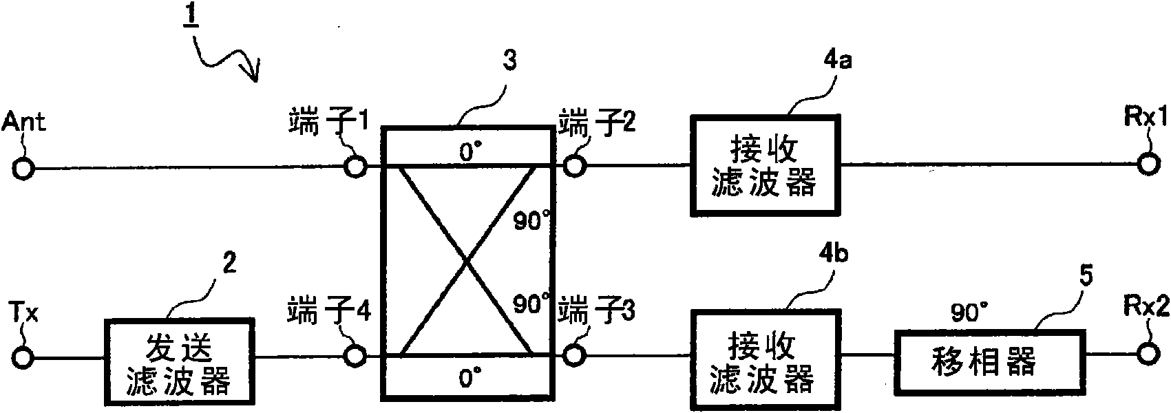
[0051] figure 1 It is a diagram showing a schematic configuration of a duplexer according to the first embodiment. The duplexer 1 includes: a hybrid 3 , a transmission filter 2 , reception filters 4 a , 4 b , and a phase shifter 5 . In the duplexer 1, the terminal 1 of the hybrid 3 serves as a common terminal Ant. The transmission filter 2 is connected between the terminal 4 of the mixer 3 and the transmission terminal (transmission signal terminal) Tx. A reception filter 4 a is connected between the terminal 2 of the hybrid 3 and the reception terminal Rx1 . The receiving filter 4 b and the phase shifter 5 are connected between the terminal 3 of the mixer 3 and the receiving terminal Rx2 . The phase shifter 5 has a function of delaying the phase of a signal by 90°.

[0052] The pass frequency of the transmission filter 2 and the pass frequencies of the receive filters 4 a and 4 b are set according to the application of the duplexer 1 , and these pass frequencies are diff...

no. 2 approach

[0082] figure 1 It is a diagram showing the circuit configuration of the duplexer 10 of the second embodiment. exist Figure 8 in, for with figure 1 The same parts are marked with the same reference numerals. exist Figure 8 In the shown duplexer 10 , a mixer 31 is further connected to the receiving terminal side of the receiving filter 4 a and the receiving filter 4 b. The mixer 31 is a 90° mixer having the same function as the mixer 3 , and has a terminal 5 , a terminal 6 , a terminal 7 , and a terminal 8 . Terminal 5 is connected to reception filter 4a, and terminal 8 is connected to reception filter 4b. The terminal 6 is connected to the receiving terminal Rx1, and the terminal 7 is connected to the receiving terminal Rx2.

[0083] A terminating resistor 12 is connected to the receiving terminal Rx1 connected to the terminal 6 of the mixer 31 . As a result, the reception terminal Rx1 is terminated without reflection. Therefore, the reception terminal Rx2 becomes ...

example 1

[0106] Figure 12 is to show the figure 1 A diagram of the structure when the duplexer 1 shown is mounted on a ceramic substrate. exist Figure 12 In the shown example, the mixer 3a and the phase shifter 5a are formed on the ceramic substrate 13 in a distributed constant type.

[0107] Specifically, the hybrid 3 a is a branch line coupler formed by connecting the terminals 1 and 2 , the terminals 2 and 3 , the terminals 3 and 4 , and the terminals 1 and 4 on the ceramic substrate 13 with distributed constant lines. Branch line coupler configurations are not limited to Figure 12 . For example, in order to save space, distributed constant lines connecting the respective terminals 1 to 4 may be bent and formed. In addition, it is also possible to configure a configuration in which a distributed constant line is added to expand the usable frequency band. In addition, distributed constant lines may also be formed on the inner layer of the ceramic substrate.

[0108] The ph...


PUM


Abstract

A duplexer (1) includes a common terminal (Ant), receiving filters (4a, 4b), a transmitting filter (2), and a hybrid (3) having four terminals (TERMINALS 1 to 4). The first terminal (TERMINAL 1), serving as one of the four terminals of the hybrid (3), is connected to the common terminal (Ant). The second and third terminals (TERMINALS 2, 3), to which a signal supplied to the first terminal is transmitted, are connected to the receiving filters (4a, 4b). The forth terminal (TERMINAL 4) of the hybrid (3) is connected to the transmitting filter (2). Consequently, the isolation of the duplexer can be improved while preventing an increase in the number of parts and complication.

Description

technical field [0001] The present invention relates to a duplexer connected to an antenna of a communication device typified by a cellular phone, a module including the duplexer, and a communication device. Background technique [0002] Figure 18 It is a figure which shows the structure of the conventional duplexer. A conventional duplexer 81 includes a transmission filter 82 connected between a common terminal Ant and a transmission terminal Tx, a reception filter 83 connected between a common terminal Ant and a reception terminal Rx, and a matching circuit 84 . When the duplexer 81 is used, for example, in a mobile phone, the common terminal Ant is connected to the antenna 94 . The transmission terminal Tx is connected to the transmission circuit 93 , and the reception terminal Rx is connected to the reception circuit 92 via the balanced output filter 91 . [0003] In the figure, arrow Y1 shows the flow of the transmission signal. Since the passband of the transmit fi...

Claims


Application Information

Patent Timeline
Patent Type & Authority Applications(China)
IPC IPC(8): H03H7/46H04B1/40
CPCH04B1/48H03H7/48H03H7/463H01P1/213H01P5/227H03H9/0028H03H9/6483H03H7/0115H03H7/1775
Inventor 井上将吾堤润
Owner TAIYO YUDEN KK
Why Eureka
Try Eureka