

Air guide structure of motorcycle
An air guide structure, motorcycle technology, applied in bicycle accessories, bicycle auxiliary equipment, climate guards and other directions, can solve the problem of inability to control the flow of driving wind, and achieve the effects of simple structure, improved comfort, and improved engine performance
Active Publication Date: 2010-08-11
HONDA MOTOR CO LTD
View PDF1 Cites 12 Cited by
- Summary
- Abstract
- Description
- Claims
- Application Information
AI Technical Summary
Problems solved by technology
In the above-mentioned conventional example, although the grille opening is formed in the shroud covering a part of the side of the fuel tank, this structure only allows the traveling air to flow in a certain direction, and the opening cannot actively control the flow of the traveling air.
Method used
View moreImage
Smart ImageViewing Examples

Examples
Embodiment Construction
Login to View More PUM
 Abstract
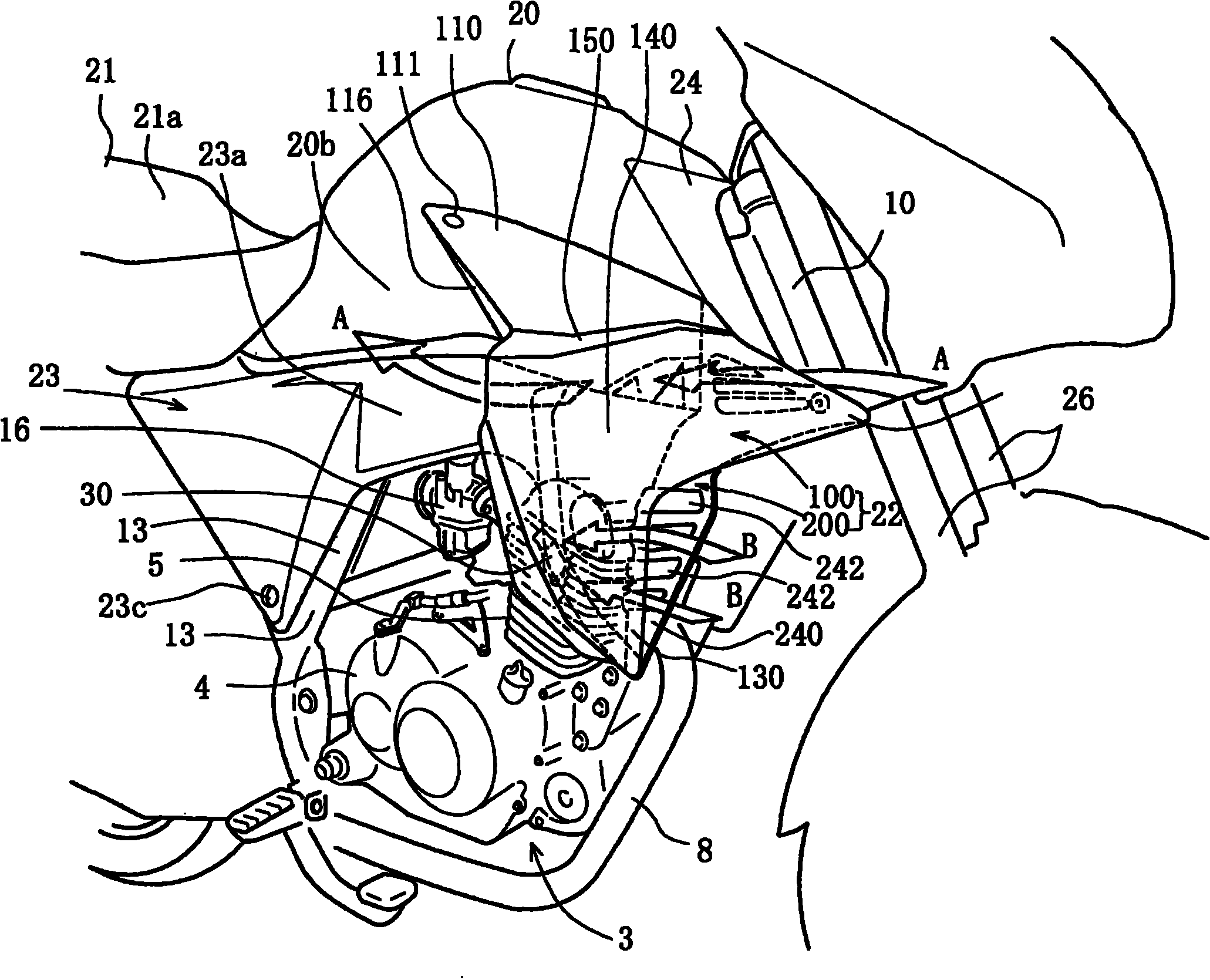
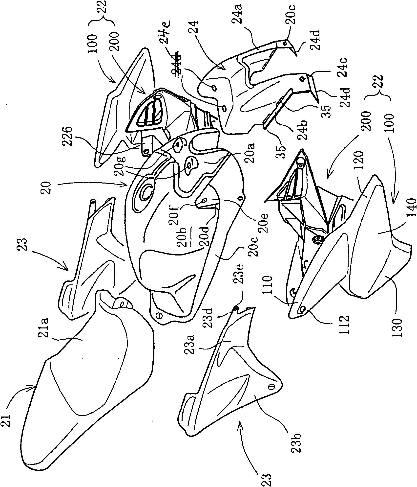
The invention provides an air guide structure of a motorcycle. Running air is divided into air towards a driver and air for cooling an engine in a simple structure by a shield. An outer shield (100) and an inner shield (200) form a shield (22) for covering each front lateral surface of a fuel tank (20) and a cylinder (5). The inner shield (200) is provided with a first air guide part (210) on theupper part and a second air guide part (240) on the lower part, and each air guide part receives the running air. The running air is received in a first ventilation passage between the outer shield (100) and the inner shield (200) from a first air guide port (210) by the first air guide part (210), is bent towards the oblique upper part to flow to the rear part, flows out of the rear part from anexhaust outlet, and faces a driver seat (21a) through the lateral surface of the fuel tank (20). The lower part of the shield (22) is provided with a second ventilation passage which bends the running air received to the second air guide passage from an air guide port (242) of a second ventilation part (24) to the oblique rear part and the lower part, and the running air flows to the lateral surface of the cylinder (5) of an air-cooled engine to perform cooling.
Description
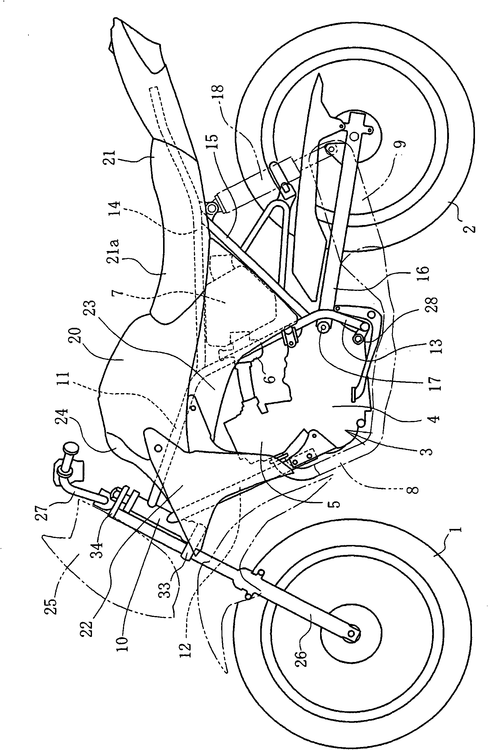
Wind guide structure of two-wheeled motorcycle technical field The present invention relates to an air guide structure of a motorcycle realized by a shroud covering the side of a fuel tank, and more particularly relates to an air guide structure capable of guiding traveling wind to both a driver and an engine. Background technique In a shroud structure that covers a part of the side of a fuel tank, a grill opening penetrating inside and outside is provided in a part of the shroud, and a structure in which traveling wind flows rearward through the grill opening is known. Patent Document 1: Japanese Patent Laid-Open No. 2007-320427 In the conventional example described above, the grille opening is formed in the shroud covering a part of the side of the fuel tank. However, this structure only allows the traveling air to flow in a certain direction, and the opening cannot actively control the flow of the traveling air. However, if the traveling wind can be controlled so as ...
Claims
Login to View More Application Information
Patent Timeline
 Patent Type & AuthorityApplications(China)
IPC IPC(8): B62J17/00B62J23/00B62J35/00
CPCB62J17/00B62J23/00B62J35/00
Inventor熊田昌弘铃木慎也横森哲人
OwnerHONDA MOTOR CO LTD