
Clamping device

A clamping device and clamping technology, which is applied in the direction of drilling equipment, earthwork drilling, drill pipe, etc., can solve the problems of troublesome operation, low degree of automation, and large range of activities, so as to reduce occupied space, compact device structure, Improve the effect of size range

Active Publication Date: 2012-08-29
HONGHUA OIL & GAS ENG SERVICE SICHUAN
View PDF7 Cites 0 Cited by
  • Summary
  • Abstract
  • Description
  • Claims
  • Application Information

AI Technical Summary

Problems solved by technology

[0003] At present, onshore oil drilling mostly uses cranes and wire ropes to move drilling tools. Using this method to move drilling tools has low moving efficiency, high labor intensity for operators, and considerable safety hazards; Oil drilling modules mostly use lifting equipment and drilling tool clamping devices to move drilling tools, but the existing clamping devices usually have the following defects: 1. When the clamping part is opened and closed, the left and right claws rotate at the same time, As a result, the front part has a large range of motion in the width direction. When the drilling tools are tightly arranged and the gap between the drilling tools is small, the clamping part is easy to contact with the adjacent drilling tool when clamping the drilling tool. Affect the clamping effect of the clamping device on the drilling tool, and even cause the phenomenon that it cannot be clamped; 2. The clamped drilling tool lacks the support and fixation of its third point, usually only by the arc surface of the clamping part To fix the drilling tool, when the size of the drilling tool is quite different from the size of the clamping part, the fixing effect is very unstable, and it is easy to cause the drilling tool to slip; 3. Since the clamping device itself cannot rotate, when the longitudinal direction of the clamping device When there is an angle between the center line and the axial center line of the drilling tool, the operation is more troublesome. Usually, manual adjustment is required before clamping. The degree of automation is low and the work efficiency is low.

Method used


Image

  • Clamping device
  • Clamping device
  • Clamping device

Examples


Embodiment Construction

[0029] Below in conjunction with accompanying drawing, the present invention is described in detail.

[0030] In order to make the object, technical solution and advantages of the present invention clearer, the present invention will be further described in detail below in conjunction with the accompanying drawings and embodiments. It should be understood that the specific embodiments described here are only used to explain the present invention, not to limit the present invention.

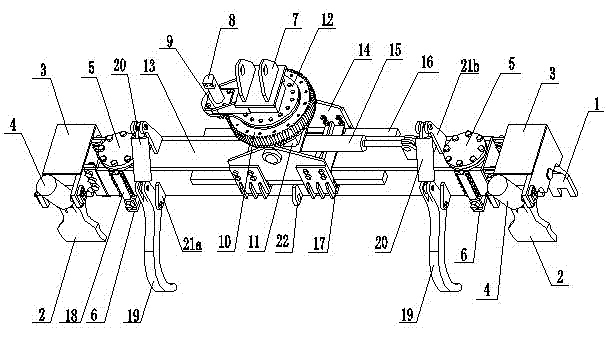
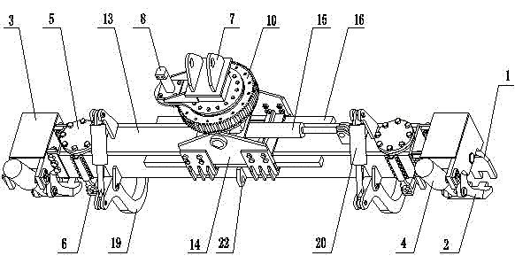
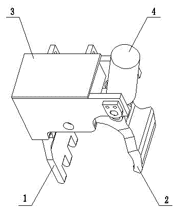
[0031] like figure 1 and 2 As shown, a clamping device includes a lifting ear 7, an arm frame and a clamping mechanism. The lifting ear 7 is arranged at the axial center position of the arm frame, and the clamping mechanism is respectively arranged on two sides of the arm frame. end, such as image 3 and 4 As shown, the clamping mechanism includes a fixed claw 1, a movable claw 2, a mounting frame 3 and a clamping drive device 4, the clamping drive device is a clamping oil cylinder, and the fi...


PUM


Abstract

The invention discloses a clamping device comprising hanging ears, an arm support and clamping mechanisms. The hanging ears are arranged on the arm support; the clamping mechanisms are respectively arranged on two ends of the arm support; each clamping mechanism comprises two clamping parts, a mounting bracket and a clamping driving device; one clamping part is connected with the mounting bracket, and the other clamping part is articulated with the clamping driving device; and the clamping part which is articulated with the clamping driving device is also articulated with the mounting bracket. Because the clamping mechanisms are designed, when clamping, the clamping device can not interfere with drilling tools which are arrayed adjacently and can not be restricted by the gaps formed due to the array of the drilling tools. In addition, because the clamping device is supported on three points by supporting mechanisms which are matched with the clamping mechanisms, the clamping device greatly improves the drilling tool clamping size range. The clamping device has compact structure and high work efficiency, can clamp the drilling tools reliably and can realize the automation.

Description

technical field [0001] The invention relates to an automation device in oil drilling equipment, in particular to a clamping device for moving drilling tools. Background technique [0002] In the petroleum industry and offshore engineering, the movement of drilling tools is a very common work step. [0003] At present, onshore oil drilling mostly uses cranes and wire ropes to move drilling tools. Using this method to move drilling tools has low moving efficiency, high labor intensity for operators, and considerable safety hazards; Oil drilling modules mostly use lifting equipment and drilling tool clamping devices to move drilling tools, but the existing clamping devices usually have the following defects: 1. When the clamping part is opened and closed, the left and right claws rotate at the same time, As a result, the front part has a large range of motion in the width direction. When the drilling tools are tightly arranged and the gap between the drilling tools is small, t...

Claims


Application Information

Patent Timeline
Patent Type & Authority Patents(China)
IPC IPC(8): E21B19/06
Inventor 陈崇魏双会高杭陈俊
Owner HONGHUA OIL & GAS ENG SERVICE SICHUAN
Learn More