
Step type variable speed scanning method for accuracy control of laser bend forming

A precision control, bending forming technology, applied in laser welding equipment, manufacturing tools, welding equipment and other directions, can solve the problems that have not been reported, and achieve the effect of reducing boundary effects, high-precision laser bending forming, and realizing laser bending forming

Inactive Publication Date: 2010-08-18
SHANGHAI JIAO TONG UNIV
View PDF3 Cites 21 Cited by
  • Summary
  • Abstract
  • Description
  • Claims
  • Application Information

AI Technical Summary

Problems solved by technology

At present, the existing research mainly analyzes the causes and influencing factors of the boundary effect in laser forming, but there is no report on the measures to reduce the boundary effect phenomenon.

Method used


Image

  • Step type variable speed scanning method for accuracy control of laser bend forming
  • Step type variable speed scanning method for accuracy control of laser bend forming
  • Step type variable speed scanning method for accuracy control of laser bend forming

Examples


Embodiment 1

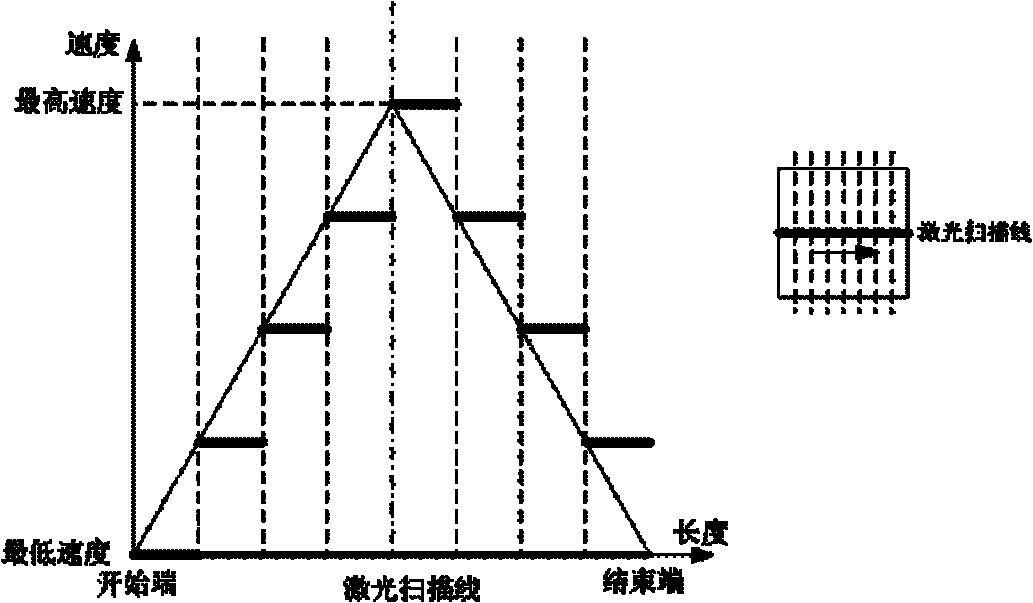
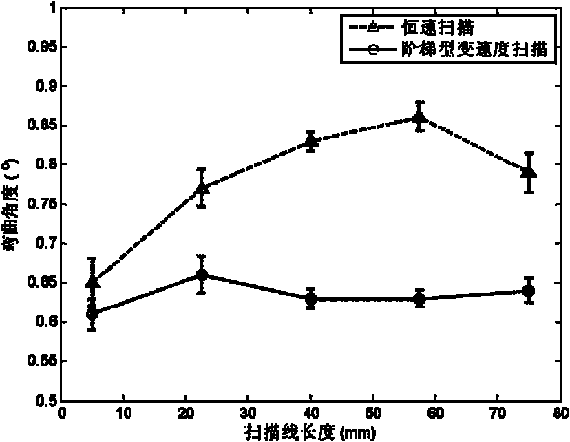
[0019] Such as figure 1 As shown, for 80×80×2mm 3 The low-carbon steel plate is scanned at variable speed, the scanning line is at the center of the plate, the length is 80mm, the laser power is 1000W, the spot diameter is 6mm, and the scanning is performed once. The operation steps are as follows:

[0020] (1) Use black hand spray paint to spray on the scanning area, and use a clamp for unilateral clamping.

[0021] (2) Taking the scanning speed of 30mm / s as the reference speed, the minimum and maximum scanning speeds in the variable speed scanning are 20mm / s and 40mm / s; the 80mm long scanning line is divided into 8 sections, each section is 10mm, therefore, the formation The speed of each section of the stepped variable speed scanning method is: 20mm / s, 25mm / s, 30mm / s, 35mm / s, 40mm / s, 35mm / s, 30mm / s, 25mm / s; through laser numerical control processing system to realize step-variable speed scanning.

[0022] (3) After completely cooling naturally, use the laser displacement...

Embodiment 2

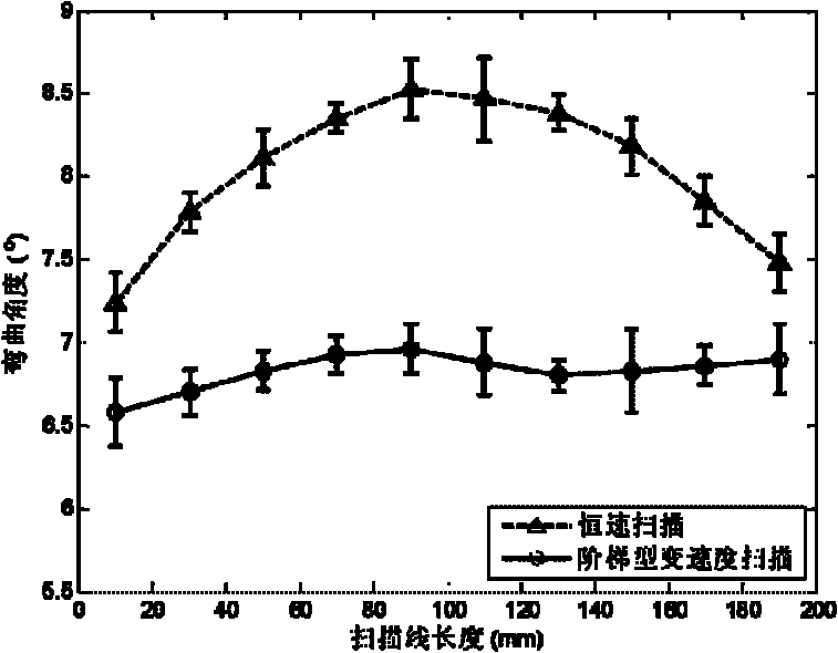
[0024] For 200×200×2mm 3 The low-carbon steel plate is scanned at a variable speed. The scanning line is at the center of the plate, the length is 200mm, the laser power is 1000W, the spot diameter is 6mm, and the scanning is repeated 10 times. The operation steps are as follows:

[0025] (1) Use black hand spray paint to spray on the scanning area, and use a clamp for unilateral clamping.

[0026] (2) The scanning speed is 30mm / s as the reference speed, and the minimum and maximum scanning speeds in the variable speed scanning are 20mm / s and 40mm / s; the 200mm long scanning line is divided into 8 sections, each section is 25mm, therefore, the formation The speed of each section of the stepped variable speed scanning method is: 20mm / s, 25mm / s, 30mm / s, 35mm / s, 40mm / s, 35mm / s, 30mm / s, 25mm / s; through laser numerical control processing The system realizes step-type variable speed scanning and repeats scanning 6 times.

[0027] (3) After completely cooling naturally, use the lase...


PUM


Abstract

A step type variable speed scanning method for accuracy control of laser bend forming belongs to the technical field of plastic forming. A laser coating material is coated on the scanning area of a surface to be scanned, a sheet material to be detected is clamped on one side, the scanning speed of the scanning area is determined by the diagram method to generate the step type variable speed scanning scheme corresponding to the scanning area, and finally the sheet material to be detected is scanned and processed according to the step type variable speed scanning scheme in a laser numerical control manner. The measure and check after processing are performed after the sheet material is cooled naturally. The method of the invention can effectively reduce the phenomenon of border effect, enhance the forming accuracy of the sheet material, thereby realizing the different energy output of the different heating area to balance the geometric constraint of the sheet material and improve the border effect.

Description

technical field [0001] The invention relates to a method in the technical field of plastic forming, in particular to a step-type variable-speed scanning method for laser bending forming precision control. Background technique [0002] Laser bending forming technology originated from the water and fire bending technology in the shipbuilding industry. It is a non-contact and moldless forming technology. The surface of the material is heated at a local high temperature by the laser beam, and the thermal stress is induced to cause the material to undergo plastic deformation, thereby realizing the forming of the metal material. . This technology can realize the forming of the complex three-dimensional curved surface of the plate by using the combined scanning method of the laser beam straight line and curve. Therefore, laser bending forming technology has great application prospects in the fields of aerospace, ships and microelectronics. [0003] At present, the research of las...

Claims


Application Information

Patent Timeline
Patent Type & Authority Applications(China)
IPC IPC(8): B23K26/00B21D5/00B23K26/082
Inventor 沈洪胡俊姚振强
Owner SHANGHAI JIAO TONG UNIV
Learn More