
Parallel horn contact system

A contact system and contact technology, applied in advance contact arrangements, transformers, electrical components, etc., can solve the problems of short service life of tap changers, increased switch maintenance and material consumption, burning of main on-off contacts, etc.

Active Publication Date: 2012-01-11
SHANGHAI HUAMING POWER EQUIP CO LTD
View PDF0 Cites 0 Cited by
  • Summary
  • Abstract
  • Description
  • Claims
  • Application Information

AI Technical Summary

Problems solved by technology

Due to the on-off of the transition contact and the main on-off contact and the fixed contact, an arc is generated, causing the transition contact and the main on-off contact to burn out, resulting in a short service life of the tap changer, and also prone to power supply accidents
At the same time, the arc pollutes the transformer oil in the switch oil chamber, which increases the maintenance and material consumption of the switch

Method used


Image

  • Parallel horn contact system
  • Parallel horn contact system
  • Parallel horn contact system

Examples


Embodiment Construction

[0017] In order to make the technical means, creative features, goals and effects achieved by the present invention easy to understand, the present invention will be further described below in conjunction with specific illustrations.

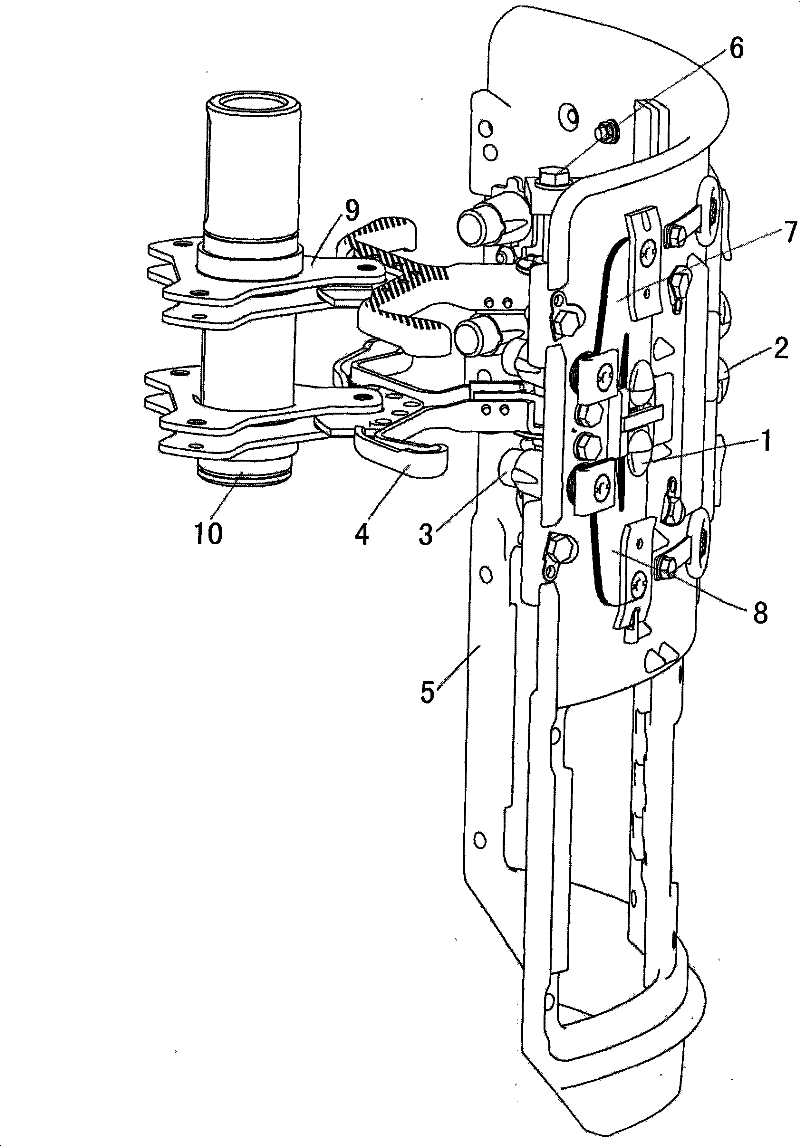
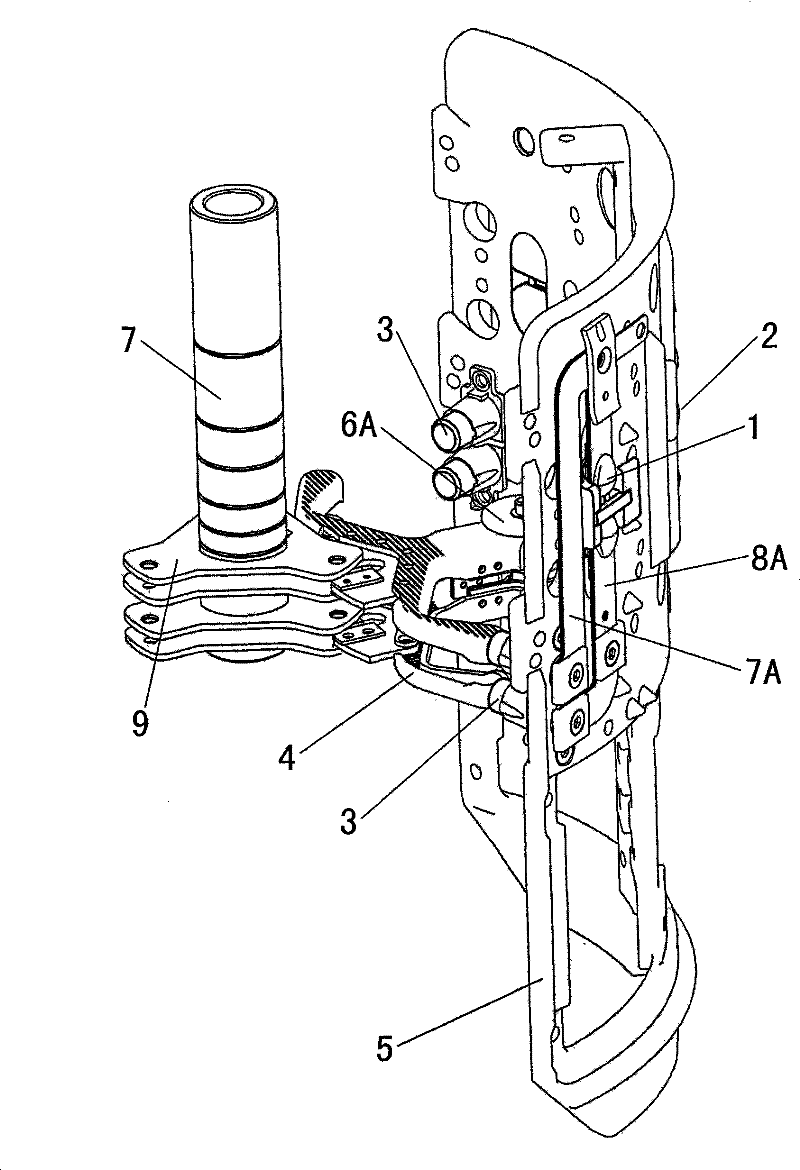
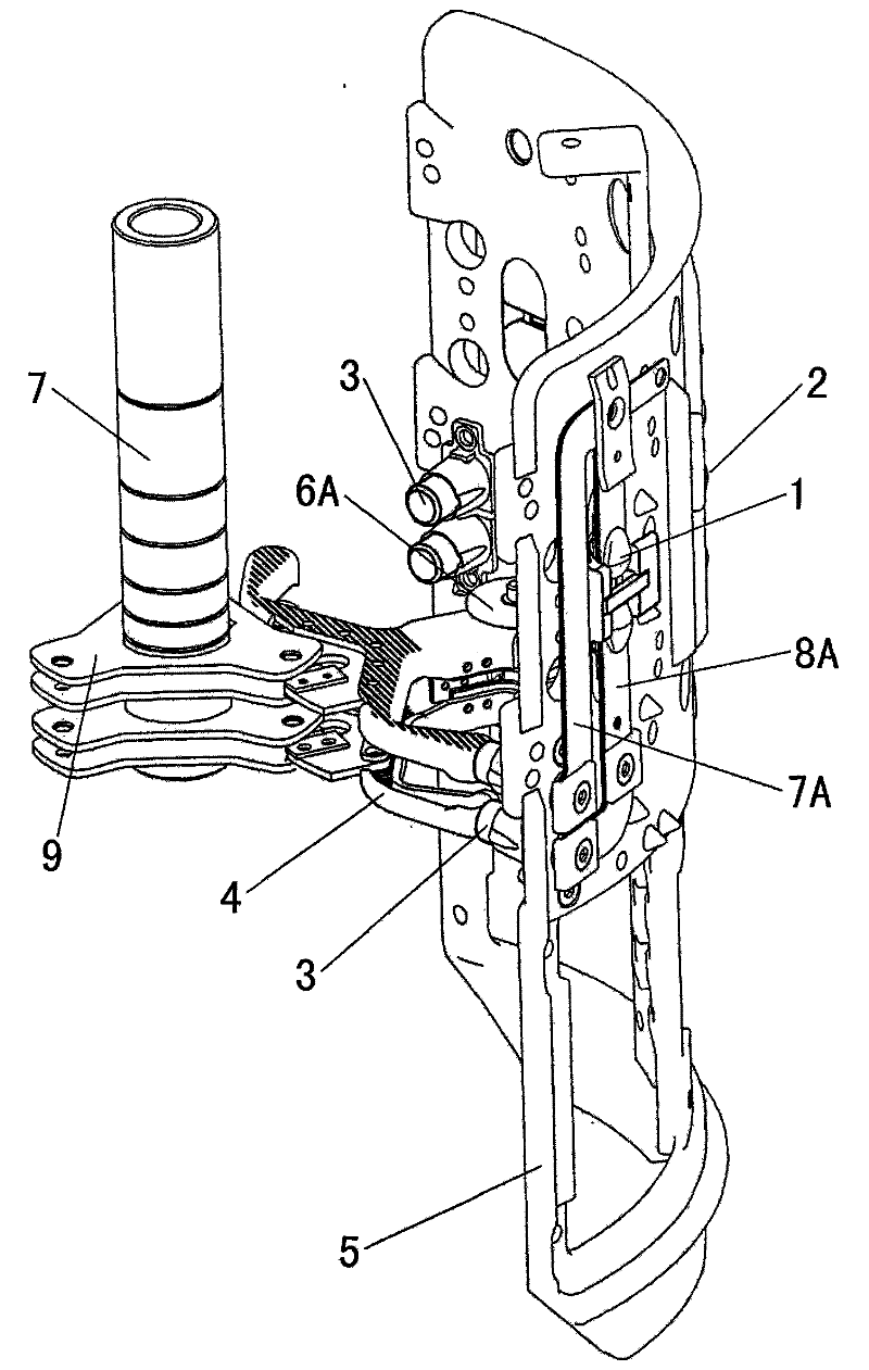
[0018] see figure 2 , the horn parallel contact system, including arc plate 5, two flexible connecting sheet groups 7A, 8A, two sets of fixed contacts 1, two pairs of bullet contacts 3, two horn contacts 4, a set of neutral points Contact 2, contact bracket 6A.

[0019] The shape and size of each arc-shaped plate 5 are the same as those of the original on-load tap-changer, so as to adapt to the diverter switch oil chamber of the on-load tap-changer. Two groups of fixed contacts 1 have the same structure as the existing fixed contacts, and are still installed on the original position on the arc plate 5, and each group of fixed contacts 1 is divided into two.

[0020] One group of neutral point contacts 2 has the same structure as the existing ...


PUM


Abstract

The invention discloses a parallel horn contact system, comprising an arc-shaped plate and a contact system. The contact system comprises two groups of fixed contacts, two pairs of bullet contacts, two or even horn contacts, a group of neutral point contacts and a contact brackets, wherein two groups of the fixed contacts, which are structurally identical to current fixed contacts, are still mounted at the original positions on the arc-shaped plate; a group of the neutral point contacts, which are structurally identical to current neutral point contacts, are still mounted at the original positions on the arc-shaped plate in order to guarantee the unchanged position of a wiring pile head on original changeover switch oil chamber; the system is characterized in that two or even horn contacts are mounted in parallel at the lower part of a switch changeover core and positioned below two groups of the fixed contacts so as to make upper room for the installation of a vacuum vessel. The system guarantees the unchanged position of the fixed contacts and the neutral point contacts while solving the problem about the installation of the vacuum vessel, thereby achieving the contact of the fixed contacts and the neutral point contacts with the wiring pile head on the changeover switch oil chamber of existing series of on-load tap changers.

Description

technical field [0001] The invention relates to the technical field of on-load tap-changers for power transformers, in particular to a diverter switch oil chamber of a combined on-load tap-changer that can be directly replaced with a parallel contact system in a vacuum bubble switch core without changing it. Background technique [0002] The on-load tap-changer is used in power transformers or industrial transformers. It taps when the transformer does not interrupt the load current (that is, under load), changes the turns ratio of the transformer, and adjusts the output voltage of the transformer. [0003] Among them, the combined on-load tap-changer is composed of a diverter switch with current conversion and a tap selector for pre-selecting the tap position without current. The diverter switch includes a diverter switch core and a diverter switch oil chamber. The diverter switch core is mainly composed of a diverter switch insulating cylinder, upper and lower flanges, thre...

Claims


Application Information

Patent Timeline
Patent Type & Authority Patents(China)
IPC IPC(8): H01F29/04H01H1/56
Inventor 肖日明肖申
Owner SHANGHAI HUAMING POWER EQUIP CO LTD
Learn More