Permanent magnet high-voltage vacuum circuit breaker

A vacuum circuit breaker, permanent magnet technology, applied in high voltage air circuit breakers, high voltage/high current switches, circuits, etc., can solve the problems of long action time, cumbersome mechanism, unreliable latching, etc., and achieves convenient installation and maintenance. The overall structure is reasonable and the effect of increasing the scope of application

Inactive Publication Date: 2010-08-18
HONGXIU ELECTRIC
View PDF0 Cites 13 Cited by
  • Summary
  • Abstract
  • Description
  • Claims
  • Application Information

AI Technical Summary

Problems solved by technology

[0003] The traditional dual power switching mechanism uses two high-voltage switch cabinets plus a set of extremely complicated electrical interlocking devices to prevent parallel operation of the two circuits
This kind of dual power supply device has the following three major defects: (1) Unreliable locking: At present, the reliability of electrical interlocking is too low, and it is strictly forbidden to use it. There is no unified design specification standard for mechanical interlocking devices, and it can only be designed and modified by each locality.
(2) The operation is complicated, and it is easy to jam, causing electric accidents; (3) The investment is large, and two switch cabinets need to be purchased, and then the locking device is designed, and then refitted to the switch cabinet
The advantage of the

Method used


Image

  • Permanent magnet high-voltage vacuum circuit breaker
  • Permanent magnet high-voltage vacuum circuit breaker
  • Permanent magnet high-voltage vacuum circuit breaker

Examples


Embodiment 1

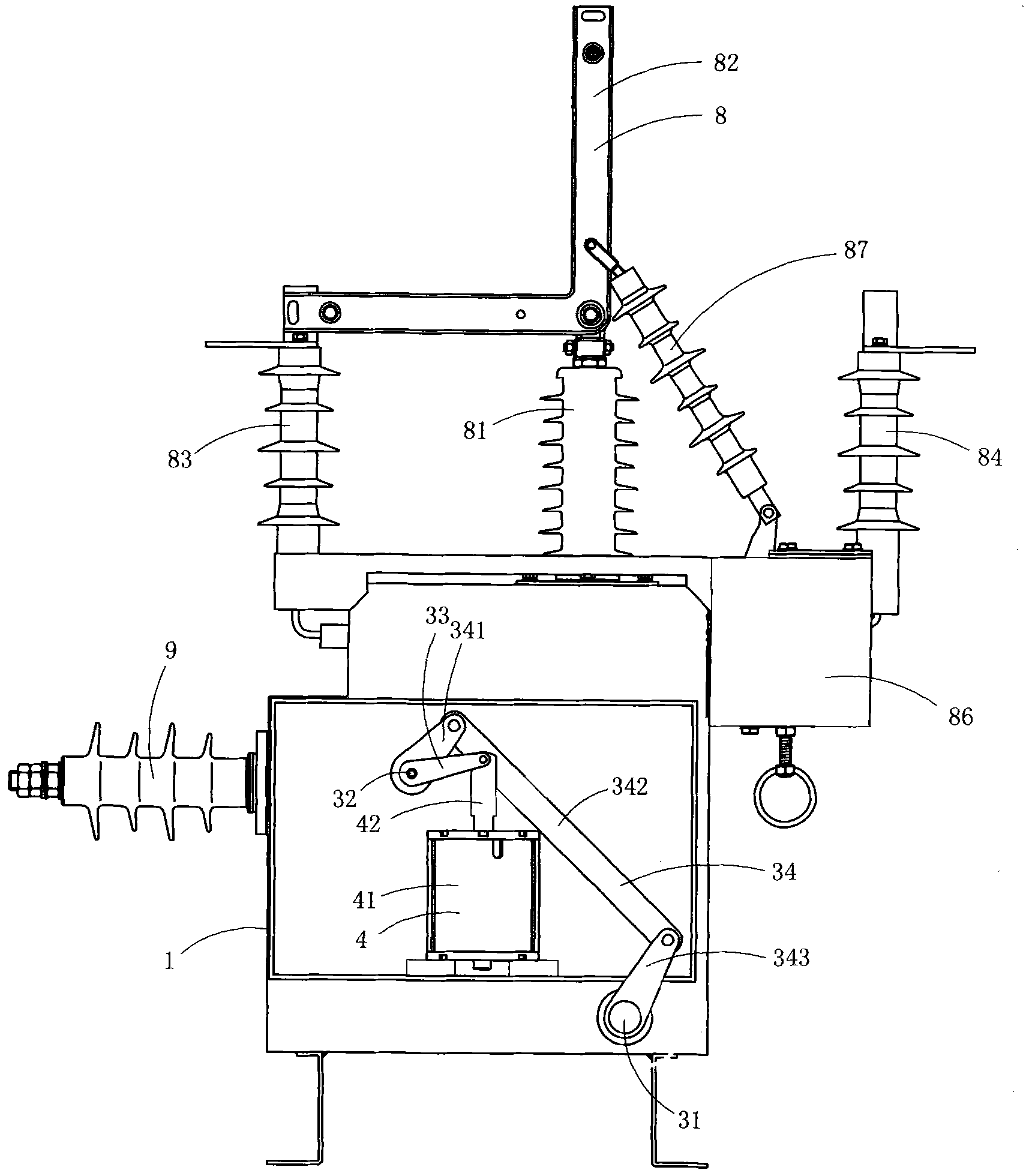
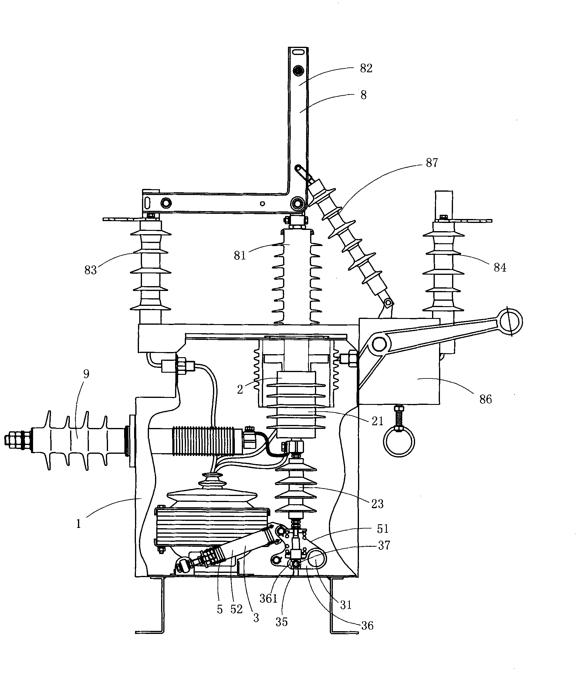
[0029] figure 1 and figure 2 A specific embodiment of the invention is shown in which, figure 1 It is a structural schematic diagram of the first structure of the present invention; figure 2 for figure 1 A schematic diagram of the structure of the permanent magnet high-voltage vacuum circuit breaker when viewed from another angle after some components are removed.

[0030] This embodiment is a permanent magnet high voltage vacuum circuit breaker, see figure 1 and figure 2 , including housing 1, vacuum arc extinguishing mechanism 2, operating mechanism 3, permanent magnet drive device 4 and buffer mechanism 5.

[0031] See figure 1 and figure 2 , each of the vacuum interrupter mechanisms 2 includes a vacuum interrupter 21, and an insulating pull rod 23 for driving the moving contact in the vacuum interrupter 21 to move in a straight line; the insulating pull rods 23 are arranged vertically;

[0032]The permanent magnet driving device 4 includes a body 41 and a drive...

Embodiment 2

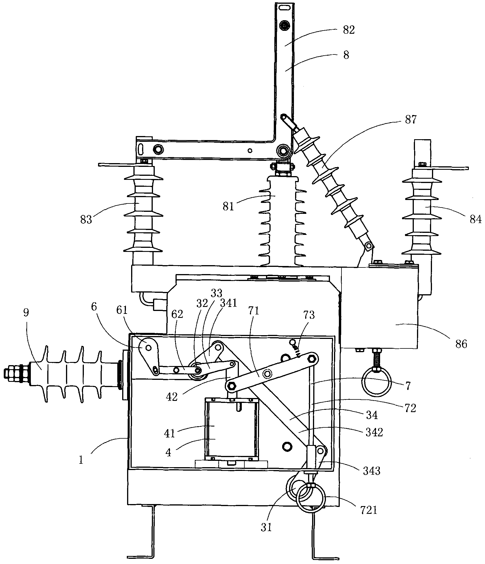
[0041] image 3 It is a structural schematic diagram of the second structure of the present invention, showing the second specific implementation mode of the present invention.

[0042] This embodiment is basically the same as Embodiment 1, the difference is: see image 3 , the vacuum circuit breaker also includes an opening and closing indicating mechanism 6 and a manual opening mechanism 7 .

[0043] The opening and closing indicating mechanism 6 includes an opening and closing indicator 61 and a linkage rod 62 which are rotatably arranged on the housing 1; one end of the linkage lever 62 is connected with the opening and closing indicator 61, and the other end is fixed on the driving auxiliary on axis 32. The indicating mechanism is relatively simplified, and the installation and maintenance are relatively convenient.

[0044] The manual opening mechanism 7 includes an opening operating lever 71, a manual pull rod 72, and a return spring 73 for resetting the opening oper...


PUM


Abstract

The invention discloses a permanent magnet high-voltage vacuum circuit breaker, which comprises a shell, vacuum arc quenching mechanisms, an operating mechanism and a permanent magnet driving device, wherein each vacuum arc quenching mechanism comprises an insulating pull rod for driving a moving contact to make rectilinear motion, and the permanent magnet driving device comprises a body and a driving rod which makes rectilinear reciprocating motion; each insulating pull rod is vertically arranged, and the driving rod in the permanent magnet driving device is vertically arranged and makes rectilinear motion along the vertical direction, and the operating mechanism comprises a driving main shaft, a driving auxiliary shaft, a driving arm and a rocker arm component; the driving rod in the permanent magnet driving device drives the driving auxiliary shaft through the driving arm, and the driving auxiliary shaft drives the driving main shaft to rotate through the rocker arm component; an output rocker arm is fixed on the driving main shaft, and the driving main shaft directly drives the insulating pull rod to make rectilinear motion along the vertical direction through the output rocker arm so as drive the moving contact to carry out the opening and closing operation. The invention has the advantages of simplified structure, fewer parts and higher reliability.

Description

technical field [0001] The invention belongs to the technical field of high-voltage switch structure design, and in particular relates to a permanent magnet high-voltage vacuum circuit breaker. Background technique [0002] In the power network, there are many users who have high requirements on the reliability of power supply, such as coal mines and oil refineries. Once a power outage occurs in these units, it will bring significant economic losses or even casualties to the unit. Therefore, the power supply in these units In the system, both the main power supply and the backup power supply are required. When the main power supply fails, the backup power supply must be put into power immediately to restore the power supply. In order to achieve this purpose, it is necessary to manually switch between the main power supply and the backup power supply through a dual power supply switching mechanism. or switch automatically. [0003] The traditional dual power switching mechan...

Claims


Application Information

Patent Timeline
IPC IPC(8): H01H33/66H01H33/664H01H33/666
Inventor 郑文秀苏杭
Owner HONGXIU ELECTRIC
Why Eureka
Try Eureka