Permanent-magnetic high-voltage vacuum circuit breaker
A vacuum circuit breaker, permanent magnet technology, applied in the direction of high-voltage air circuit breakers, high-voltage/high-current switches, circuits, etc., can solve the problems of unreliable locking, complicated operation, and long operating time, so as to increase the scope of application and simplify The internal structure and the effect of fewer failure sources
- Summary
- Abstract
- Description
- Claims
- Application Information
AI Technical Summary
Problems solved by technology
Method used
Image
Examples
Embodiment 1
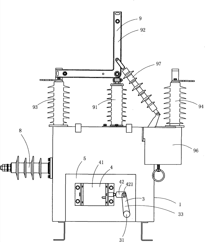
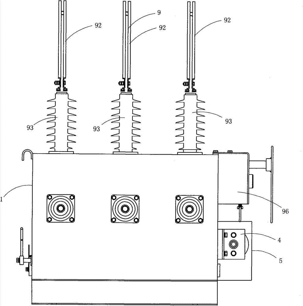
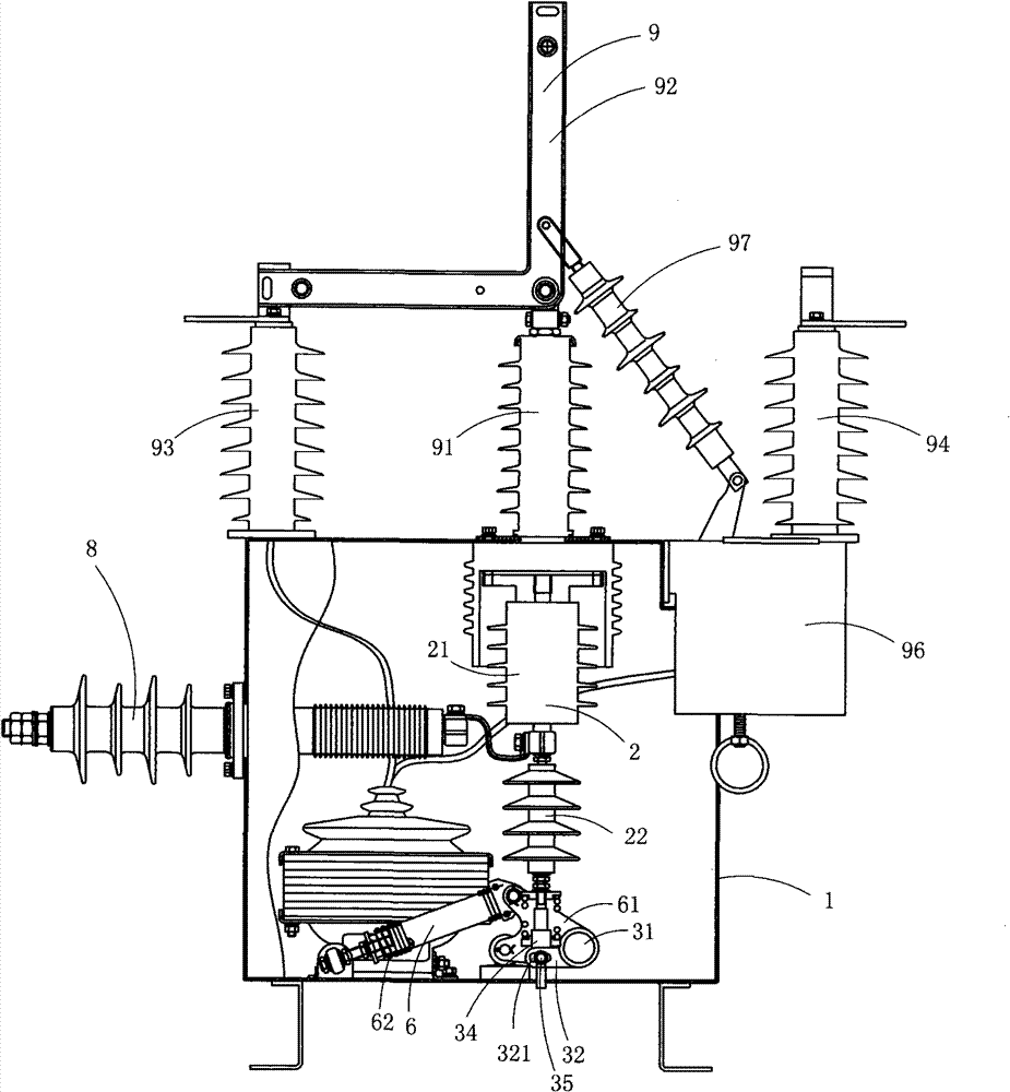
[0027] Figure 1 to Figure 3 A first embodiment of the invention is shown in which, figure 1 It is a structural schematic diagram of the first structure of the present invention; figure 2 for figure 1 A side view of the permanent magnet high-voltage vacuum circuit breaker shown; image 3 for figure 1 A structural schematic diagram of the buffer mechanism in the permanent magnet high-voltage vacuum circuit breaker shown.
[0028] This embodiment is a permanent magnet high voltage vacuum circuit breaker, see Figure 1 to Figure 3 , including housing 1, vacuum arc extinguishing mechanism 2, operating mechanism 3, permanent magnet driving device 4 and buffer mechanism 6.
[0029] Each vacuum interrupter mechanism 2 includes a vacuum interrupter 21 and an insulating pull rod 22 for driving the moving contact in the vacuum interrupter 21 to move linearly;
[0030] The operating mechanism 3 includes a drive main shaft 31, an output crank arm 32 arranged on the drive main shaft...
Embodiment 2
[0038] Figure 4 It is a structural schematic diagram of the second structure of the present invention, showing the second specific implementation manner of the present invention.
[0039] This embodiment is basically the same as Embodiment 1, except that the vacuum circuit breaker also includes a manual opening mechanism 7, and the manual opening mechanism 7 includes an opening arm 71 fixedly arranged on the driving spindle The pin shaft 721 rotates the opening cam 72 arranged on the housing 1, the handle 73 for driving the opening cam 72 to rotate, and the torsion spring (not visible in the figure) for providing the return elastic force for the opening cam 72; The handle 73 drives the opening cam 72 to rotate, and the opening cam 72 pushes the opening lever 71 to move during the rotation, thereby driving the driving main shaft 31 to rotate, thereby realizing the manual opening operation.
[0040] The handle 73 is fixed on the pin shaft 721 , the torsion spring is sheathed o...
PUM
 Abstract
Description
Claims
Application Information
 - R&D
- Intellectual Property
- Life Sciences
- Materials
- Tech Scout
- Unparalleled Data Quality
- Higher Quality Content
- 60% Fewer Hallucinations
Browse by: Latest US Patents, China's latest patents, Technical Efficacy Thesaurus, Application Domain, Technology Topic, Popular Technical Reports.
© 2025 PatSnap. All rights reserved.Legal|Privacy policy|Modern Slavery Act Transparency Statement|Sitemap|About US| Contact US: help@patsnap.com


