Training sequence reconstruction-based channel estimation method and system
A channel estimation and training sequence technology, which is applied in the field of digital information transmission, can solve the problems of limiting the multipath time extension of the estimable channel, high implementation complexity, and affecting system performance, so as to improve system spectrum utilization and system mobility performance , low anti-Doppler performance, and improved channel estimation
- Summary
- Abstract
- Description
- Claims
- Application Information
AI Technical Summary
Problems solved by technology
Method used
Image

Examples
Embodiment 1
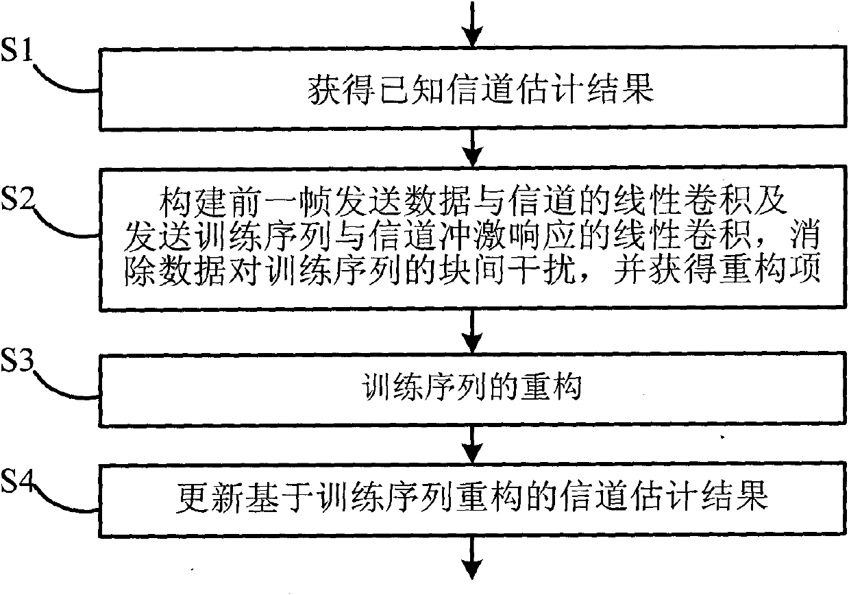
[0080] Such as Figure 4 Shown is a schematic diagram of the frame structure of a CPR-TDS-OFDM system in this embodiment. The training sequence of different signal frames at the transmitting end is designed as follows:
[0081] Guard interval Includes PN training sequence And its L-bit cyclic extension, the training sequence of adjacent frames Relative to The difference is L. Therefore, the training sequence protection sequence of the i-th signal frame The last N p Training sequence protection sequence of symbols and i+1 signal frame The top N p Symbols are This feature is determined by the phase of the training sequence of the i-th signal frame designed in the above frame structure as owned.
[0082] The frequency domain symbol to be transmitted in the i-th frame is S i (k), any symbol modulation technique can be selected. Using multi-carrier transmission, the length of the frequency domain symbols to be transmitted is N d = 3780 frequency domain data block It does not i...
Embodiment 2
[0141] Such as Figure 5 Shown is a schematic diagram of the frame structure of the TDS-SC-FDE system based on BFR sequence filling in this embodiment. Using single-carrier transmission technology, the time domain symbol to be transmitted in the i-th frame is s i [n], you can choose any symbol modulation technique. The length of time domain symbols to be transmitted is N d = 4096 time domain data block The padding length of the guard interval between time domain data blocks is N G Known guard interval sequence Including the training sequence and the cyclic extension of the training sequence, the structure of the training sequence is the same as the first embodiment. The time domain data block (frame body) and guard interval (frame header) together form a signal frame.
[0142] For the TDS-SC-FDE system based on BFR sequence filling of this embodiment, when l>L, the implementation steps of the channel estimation method based on training sequence reconstruction to eliminate resid...
Embodiment 3
[0171] Such as Image 6 Shown is a schematic diagram of the frame structure of the national standard PN420 mode of the TDS-OFDM system in this embodiment. The frequency domain symbol to be transmitted in the i-th frame is S i (k), any symbol modulation technology can be selected. Using multi-carrier transmission technology, the frequency domain symbols to be transmitted form a frequency domain data block with a length of N=3780 {S i (k)) n=0 N-1 , Does not include pilots and virtual subcarriers. Frequency domain data block {S i (k)) n=0 N-1 After inverse discrete Fourier transform, the time domain data block {s i (n)) n=0 N-1 , The guard interval between time domain data blocks is filled with a known training sequence of length M=420 {c i (n)) n=0 M-1 . The time domain data block (frame body) and guard interval (training sequence) together form a signal frame. The frame header signal length of the national standard PN420 mode is 420 symbols, which is composed of preamble, PN25...
PUM
 Abstract
Description
Claims
Application Information
 - R&D Engineer
- R&D Manager
- IP Professional
- Industry Leading Data Capabilities
- Powerful AI technology
- Patent DNA Extraction
Browse by: Latest US Patents, China's latest patents, Technical Efficacy Thesaurus, Application Domain, Technology Topic.
© 2024 PatSnap. All rights reserved.Legal|Privacy policy|Modern Slavery Act Transparency Statement|Sitemap