
Vacuum suction cup

A cupping device and vacuum technology, applied in the direction of suction equipment, heating equipment for treatment, cooling equipment for treatment, etc., can solve the problems of cupping therapy losing its warming effect and affecting the treatment effect of the affected area, so as to prevent discomfort or Burns, safety-enhancing effect

Inactive Publication Date: 2010-08-25
王卫东
View PDF0 Cites 8 Cited by
  • Summary
  • Abstract
  • Description
  • Claims
  • Application Information

AI Technical Summary

Problems solved by technology

[0006] But this vacuum cupping also has defect, because vacuum suction device creates negative pressure, so does not need fire source, but has also removed the heat source in traditional cupping simultaneously, and this just makes cupping therapy lose its warming effect, affects Therapeutic effect on the affected area

Method used


Image

  • Vacuum suction cup
  • Vacuum suction cup
  • Vacuum suction cup

Examples


Embodiment Construction

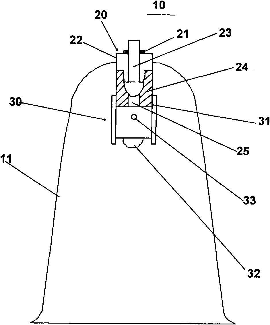
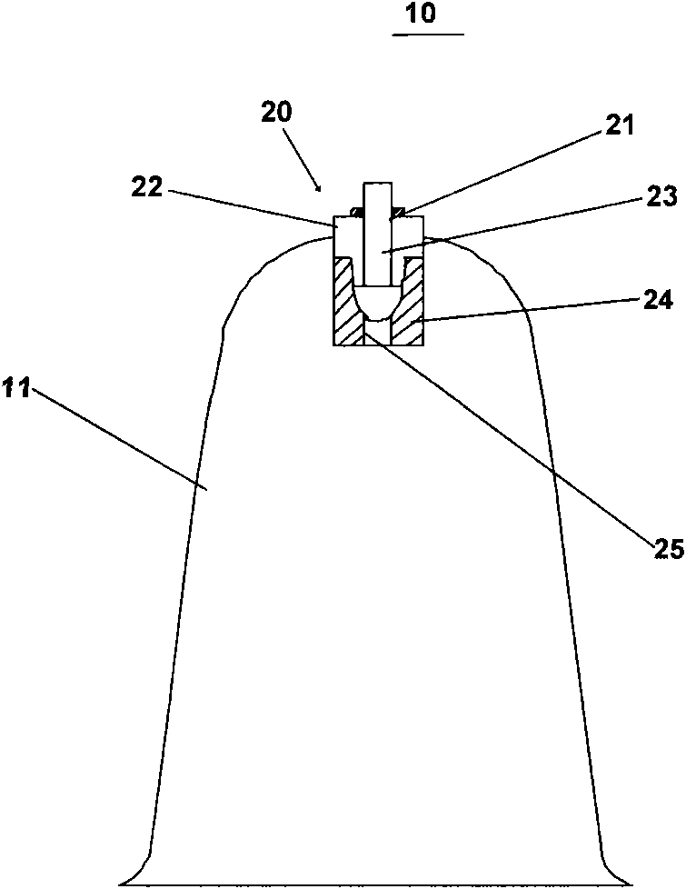
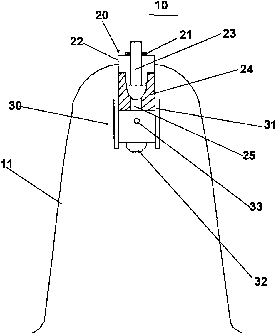
[0023] As shown in FIG. 2 , the vacuum cupping device according to the present invention is further equipped with a high-power light-emitting diode device 30 on the basis of the prior art vacuum cupping device shown in FIG. 1 . The high-power LED device 30 is accommodated in the tank body 11 to heat the inside of the tank body to realize the warming effect of the cupping device. The high-power LED device 30 includes a bracket 31 , a high-power LED 32 and an air hole 33 . The bracket 31 is used to combine the high-power LED 32 with the bottom end of the one-way valve 20 , preferably right below the one-way valve 20 . Certainly, the high-power light-emitting diode 32 only needs to be in the tank body. The air hole 33 is a through hole formed on the side wall of the bracket 31. The air hole 33 communicates with the communication hole 25, so that the air in the tank body 11 can pass through the air hole 33, the communication hole 25, the inside of the valve body 22 and the valve ...


PUM


Abstract

The invention provides a vacuum suction cup. The vacuum suction cup comprises a cup body, a one-way valve and a high-power light-emitting diode device, wherein the high-power light-emitting diode device is accommodated in the cup body, comprises a bracket, a high-power light-emitting diode and an air hole and is jointed at the bottom end of the one-way valve through the bracket; the air hole is a through hole formed on the side wall of the bracket; and a first end and a second end of the high-power light-emitting diode are electrically connected with a power supply through leads to form a high-power light-emitting diode circuit. Since the high-power light-emitting diode serving as a heat source is further arranged in the vacuum suction cup, the vacuum suction cup can provide a warming function while providing a negative pressure function. Therefore, the function of the suction cup is effectively brought into play and the vacuum cup is safe and easy to use.

Description

technical field [0001] The invention relates to a vacuum cupping device, in particular to a vacuum cupping device with a high-power light-emitting diode as a heat source. Background technique [0002] Cupping, commonly known as cupping, is a traditional Chinese medicine device that is commonly used to treat low back pain, neck and shoulder pain, rheumatic pain, stiff neck, colds, indigestion, insomnia, and menopausal syndrome. [0003] Cupping has multiple functions, mainly: 1) Mechanical stimulation. Cupping therapy creates negative pressure in the tank through exhaust, and the edge of the tank can be tightly attached to the skin surface, pulling nerves, muscles, blood vessels and subcutaneous glands, It can cause a series of neuroendocrine reactions, adjust the vasodilation and contraction function and the permeability of blood vessels so as to improve local blood circulation; 2) Negative pressure effect, the negative pressure effect of cupping can cause local rapid conges...

Claims


Application Information

Patent Timeline
Patent Type & Authority Applications(China)
IPC IPC(8): A61M1/00A61F7/00
Inventor 王卫东王子华李开元
Owner 王卫东
Learn More