Thimble structure for die-casting mould

A die-casting mold and thimble technology, which is applied in the field of thimble structure for die-casting molds, can solve problems such as difficult parts removal, and achieve the effect of improving production efficiency and simple demoulding operation

Active Publication Date: 2010-08-25
上海嘉朗实业有限公司
View PDF10 Cites 8 Cited by
  • Summary
  • Abstract
  • Description
  • Claims
  • Application Information

AI Technical Summary

Problems solved by technology

[0003] The purpose of the present invention is to provide a thimble structure for a die-casting mold. In order to solve the technical problem that it is difficult to take the parts out of the cavity of the mold w

Method used


Image

  • Thimble structure for die-casting mould
  • Thimble structure for die-casting mould
  • Thimble structure for die-casting mould

Examples


Embodiment Construction

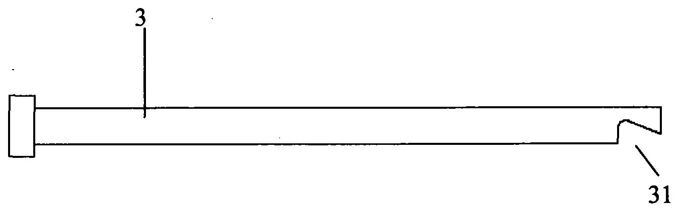
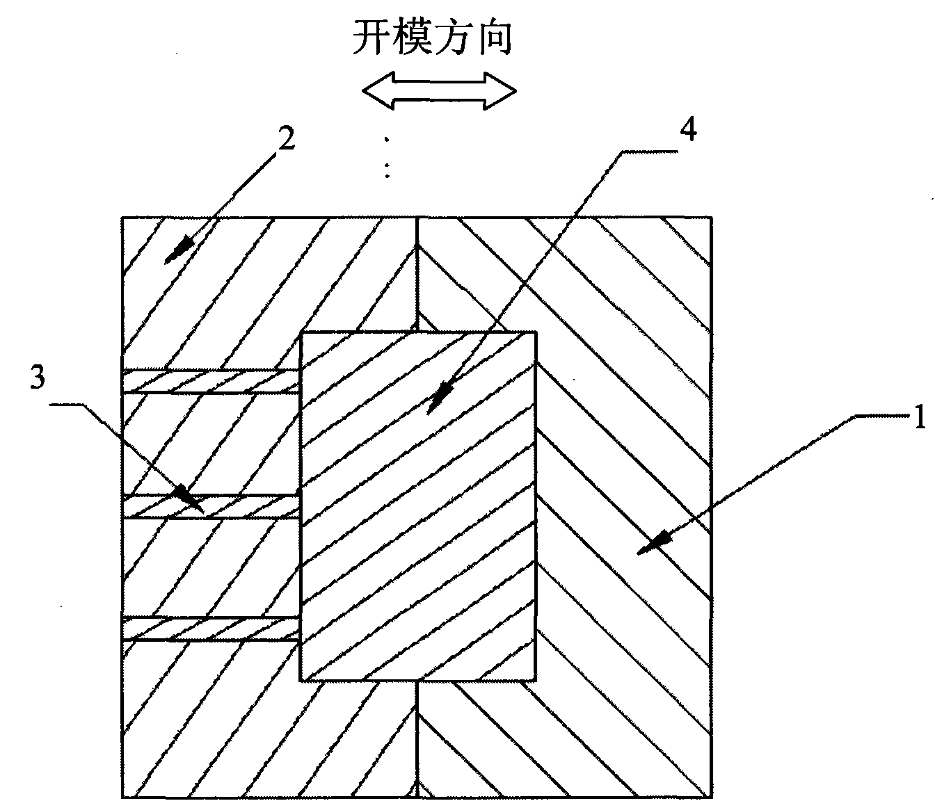
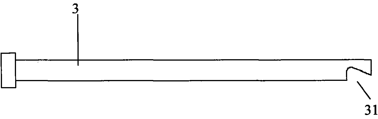
[0022] Referring to Fig. 2-6, the present invention provides a thimble structure for a die-casting mold. As shown in the figure: the die-casting mold is composed of a fixed mold 1 and a movable mold 2, and the movable mold 2 is provided with a thimble 3 that can extend to the cavity for ejection. As shown in FIG. 2 , the end of the thimble 3 near the cavity of the movable mold 2 has a barb-shaped oblique notch 31 .

[0023] As a preferred embodiment, the thimbles 3 are multiple and arranged in parallel, and the barb-shaped oblique notches 31 of the thimbles have the same direction. Of course, if the direction of the barb-shaped oblique notch 31 is slightly different, the effect may be slightly worse in the demoulding operation, but it can also be implemented.

[0024] Part demoulding operation process of the present invention is as follows:

[0025] As shown in FIG. 3 , when the molten aluminum enters the cavity, the cavity and the barb-shaped oblique gap 31 of the thimble 3...


PUM


Abstract

The invention relates to die-casting mould, in particular to a thimble structure for the die-casting mould. The die-casting mould consists of a fixed die and a moving die, wherein the moving die is provided with a thimble capable of extending to a die cavity to perform ejection movement. The thimble structure is characterized in that the one end, close to the die cavity of the moving die, of the thimble is provided with a barb-shaped skew notch. The thimble structure mainly solves the technical problem that parts can be taken out of the die cavity of the moving die very difficultly when the conventional die is used, and when the die-casting mould is opened, the parts can be taken out of the die cavity smoothly by using the thimble structure to achieve the aim of improving the product production efficiency.

Description

technical field [0001] The invention relates to a die-casting mold, in particular to a thimble structure for a die-casting die. Background technique [0002] At present, the die-casting process has been widely used in the industry and has become an important production method for many parts in the fields of automobiles and electrical instruments. It has the characteristics of fast molding speed, high work efficiency, clean environment, smooth surface, and complex molded parts. In the production process, when the mold is opened to take parts, if the friction force of the fixed mold 1 relative to the part 4 is greater than the friction force of the movable mold 2 to the part, the part 4 will stay in the fixed mold 1, because the fixed mold 1 has no thimble, and the thimble 3 is often set on the side of the movable mold 2, making it difficult to remove the part 4 from the cavity of the fixed mold 1, thus affecting production efficiency. In the current mold design, the deep cav...

Claims


Application Information

Patent Timeline
IPC IPC(8): B22D17/22
Inventor 王嵩
Owner 上海嘉朗实业有限公司
Why Eureka
Try Eureka