Non-rigid cover connecting rod

A non-rigid, connecting rod technology, applied in the direction of connecting rods, shafts and bearings, mechanical equipment, etc., can solve the problems of increasing engine vibration and noise, consuming engine mechanical power, increasing design quality, etc., to reduce vibration and noise, The effect of reducing effective mechanical work and reducing mass

Inactive Publication Date: 2010-08-25
靳北彪
View PDF6 Cites 0 Cited by
  • Summary
  • Abstract
  • Description
  • Claims
  • Application Information

AI Technical Summary

Problems solved by technology

However, under such high-speed rotation and swing, any increase in the mass of the big end of the connecting rod and the connecting rod cover will cause a sharp increase in the centrifugal force at the same time, which will not only put forward higher requirements for the strength of the crankshaft connecting rod and other components, so that it must be increased. Design quality, such a vicious circle
Moreover, the increase of centrifugal force will inevitably increase the vibration and noise of the engine. More importantly, the increase of centrifugal force will increase the distance between the main journal and the bearing bush of the crankshaft, especially between the connecting rod journal of the crankshaft and the bearing bush of the connecting rod bearing. The friction force between them consumes a lot of mechanical work of the engine

Method used


Image

  • Non-rigid cover connecting rod
  • Non-rigid cover connecting rod
  • Non-rigid cover connecting rod

Examples


Embodiment 1

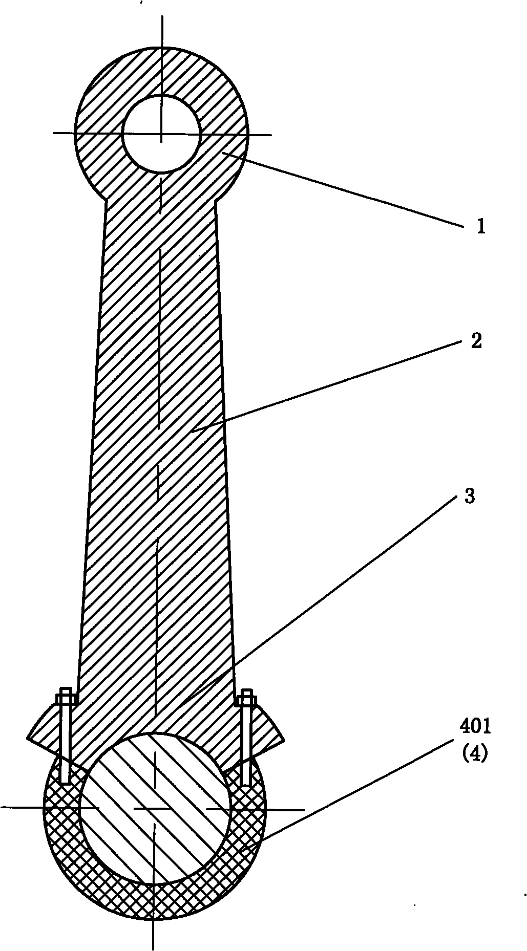
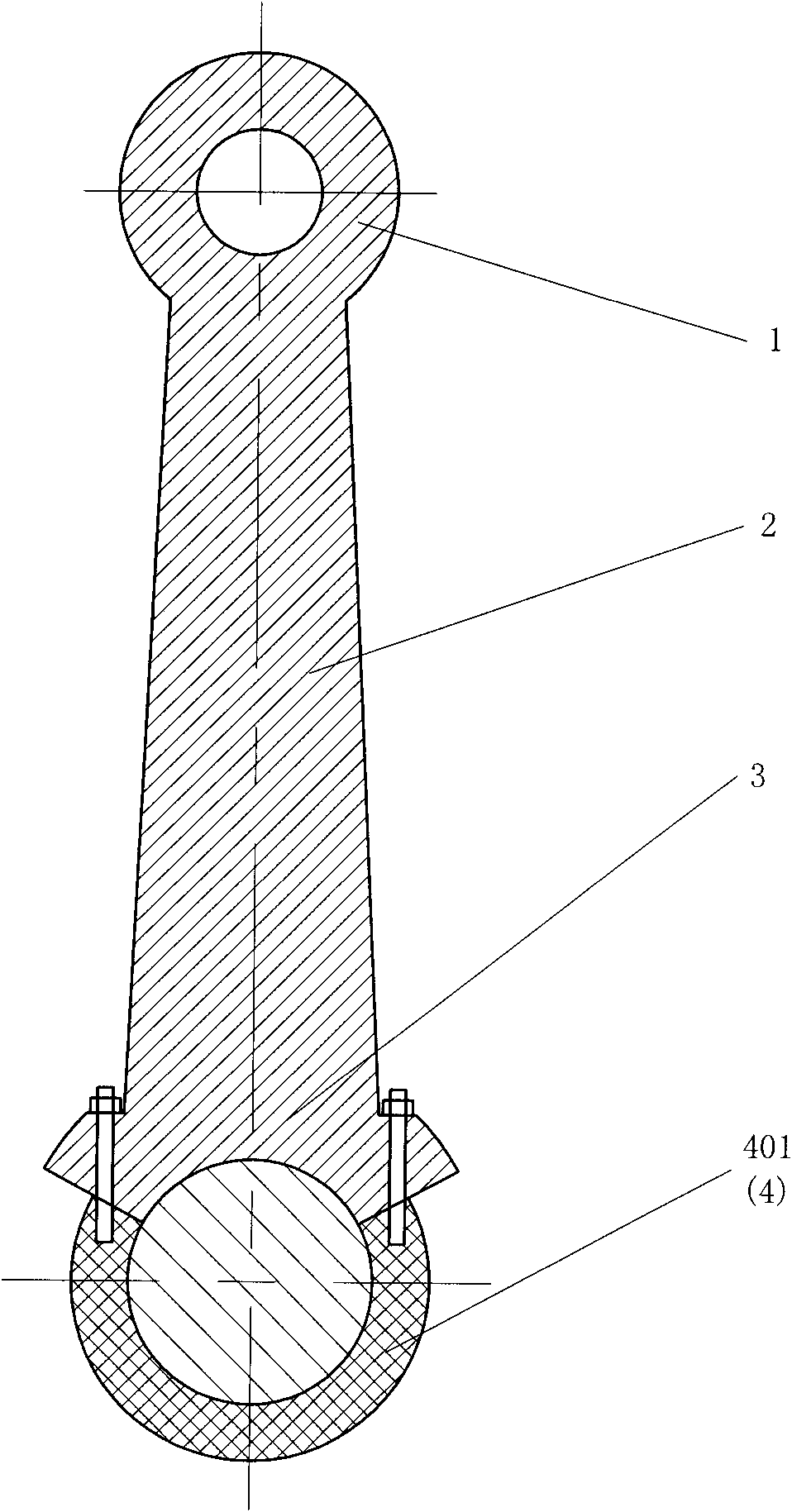
[0021] The connecting rod with non-rigid cover as shown in FIG. 1 includes a small connecting rod head 1 , a connecting rod shaft 2 , a large connecting rod head 3 and a connecting rod cover 4 , and the connecting rod cover 4 is set as a non-rigid connecting rod cover 401 . The sum of the central angles of the connecting rod big end 3 and the non-rigid connecting rod cover 401 is 360°, and the central angle of the non-rigid connecting rod cover 401 is larger than 180°. The purpose of this setting is to greatly reduce the mass of the big end of the connecting rod, reduce the friction between the crankshaft, the crank connecting rod and other components, thereby reducing the effective mechanical work consumed by the friction and improving the mechanical efficiency of the engine.

Embodiment 2

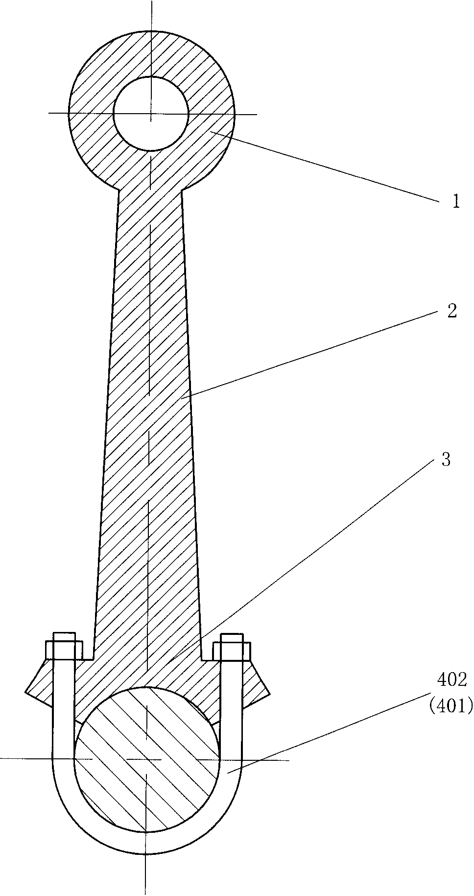
[0023] The difference between the non-rigid cover connecting rod shown in FIG. 2 , FIG. 3 and FIG. 4 is that the non-rigid connecting rod cover 401 is a rope-type connecting rod cover 402 .

Embodiment 3

[0025] The difference between the non-rigid cover connecting rod shown in FIG. 5 and the first embodiment is that the non-rigid connecting rod cover 401 is set as a chain-type connecting rod cover 403 .


PUM


Abstract

The invention discloses a non-rigid cover connecting rod comprising a connecting rod small head (1), a connecting rod body (2), a connecting rod large head (3) and a connecting rod cover (4), wherein the connecting rod cover (4) is set into a non-rigid connecting rod cover (401). The invention reduces the total design quality of an engine and the vibration and the noise of the engine and remarkably improves the mechanical efficiency of the engine.

Description

technical field [0001] The invention relates to the field of engines, in particular to a non-rigid cover connecting rod. technical background [0002] In the design of existing engines, the connecting rod head and the connecting rod journal of the crankshaft are assembled together through the rigid connecting rod cover. Due to the characteristics of the rigid connecting rod cover, the connecting rod cover and the connecting rod big end can only occupy 180-degree central angle, and due to reasons such as fixing, the quality of the connecting rod cap and the connecting rod head has to be designed to be relatively large to ensure its strength. However, under such high-speed rotation and swing, any increase in the mass of the big end of the connecting rod and the connecting rod cover will cause a sharp increase in the centrifugal force at the same time, which will not only put forward higher requirements for the strength of the crankshaft connecting rod and other components, so ...

Claims


Application Information

Patent Timeline
Patent Type & Authority Applications(China)
IPC IPC(8): F16C7/02F16C7/00
Inventor 靳北彪
Owner 靳北彪
Why Eureka
Try Eureka