High-efficiency crank connecting rod mechanism

A crank-link mechanism, high-efficiency technology, applied in the direction of the crank, connecting rod, crankshaft, etc., can solve the problems of increasing engine vibration and noise, consuming engine mechanical power, increasing design quality, etc., to reduce vibration and noise, reduce effective Mechanical work, the effect of improving mechanical efficiency

Active Publication Date: 2014-06-25
无锡市旭恒精密机械有限公司
View PDF5 Cites 0 Cited by
  • Summary
  • Abstract
  • Description
  • Claims
  • Application Information

AI Technical Summary

Problems solved by technology

However, any increase in the mass of the connecting rod cover under such high-speed rotation and swing will cause a sharp increase in the centrifugal force at the same time, which will not only put forward higher requirements for the strength of the crankshaft connecting rod and other components, so that its design quality must be increased, so Vicious circle; and the increase of centrifugal force will inevitably increase the vibration and noise of the engine; more importantly, the increase of centrifugal force will increase the crankshaft between the main journal and the bearing bush, especially the connecting rod journal and connecting rod of the crankshaft. The friction between the bearing bushes consumes a lot of mechanical work of the engine

Method used


Image

  • High-efficiency crank connecting rod mechanism
  • High-efficiency crank connecting rod mechanism
  • High-efficiency crank connecting rod mechanism

Examples


Embodiment 1

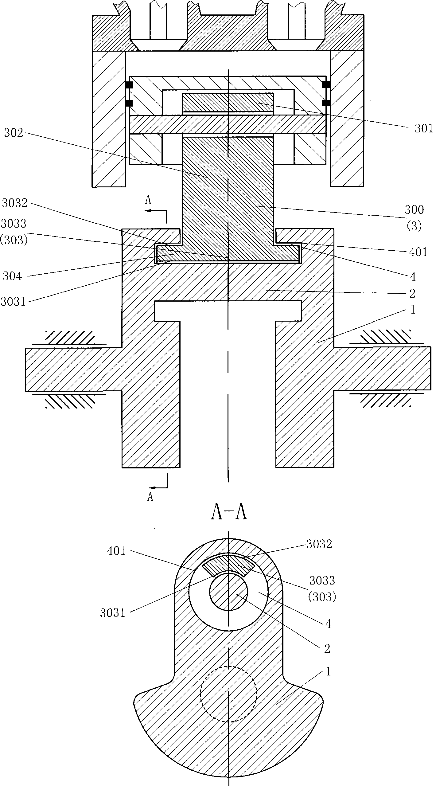
[0027] like figure 1 The high-efficiency crank-link mechanism shown includes a crank 1, a connecting rod journal 2 and a connecting rod 3. The crank 1 and the connecting rod journal 2 are integrally processed, and the crank 1 is provided with a ring around the connecting rod journal 2. Groove 4, connecting rod 3 is set as high-efficiency connecting rod 300 formed by connecting rod small head 301, connecting rod body 302 and inner and outer sides matching opening pipe wall 3033, and inner and outer sides matching opening pipe wall 3033 inner side 3031 and connecting The rod journal 2 matches. The two ends of the inner and outer sides matching the opening pipe wall 3033 are set as the pipe wall fitting end 304, and the pipe wall fitting end 304 is arranged in the annular groove 4, and the inner side 3031 of the pipe wall fitting end 304 is matched with the connecting rod journal 2, and the pipe wall The outer surface 3032 of the mating end 304 is matched with the inner surface ...

Embodiment 2

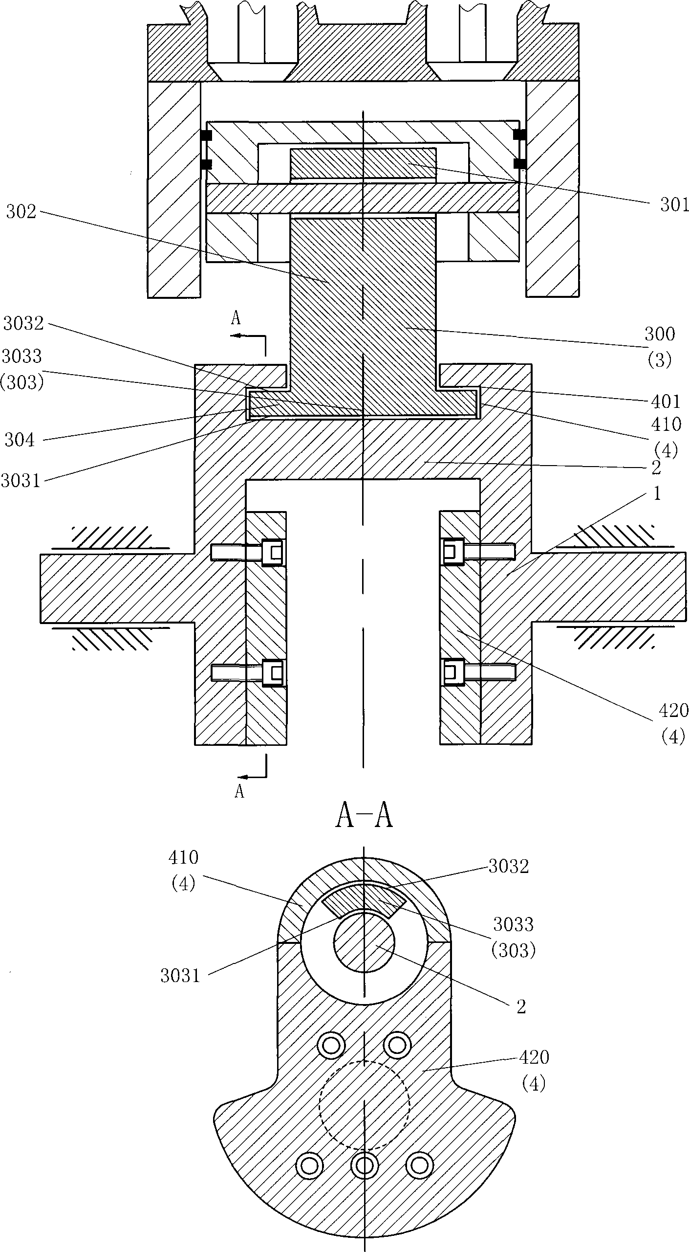
[0029] like figure 2 The difference between the shown high-efficiency crank-link mechanism and Embodiment 1 is that the annular groove 4 is set to be formed by the first semi-annular body 410 and the second semi-annular body 420; 1 is integrally processed, and the second semi-annular body 420 is set to be fixedly connected with the crank 1.

Embodiment 3

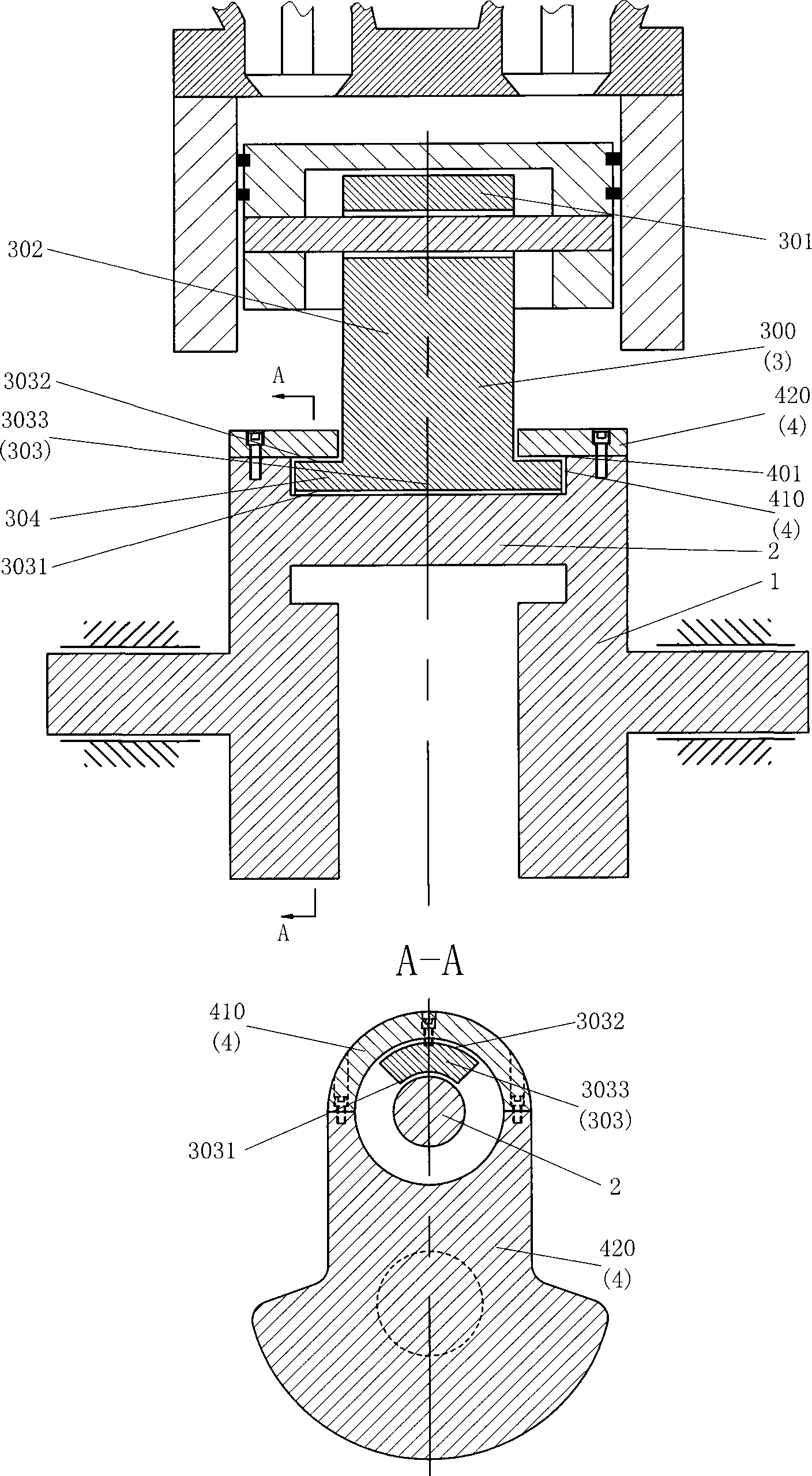
[0031] like image 3 The difference between the shown high-efficiency crank-link mechanism and Embodiment 1 is that the annular groove 4 is set to be formed by the first semi-annular body 410 and the second semi-annular body 420; 1 is fixedly connected, and the second semi-annular body 420 is set to be integrally processed with the crank 1.


PUM


Abstract

A high-efficiency crank connecting rod mechanism comprises a crank (1), a connecting rod journal (2) and a connecting rod (3). The crank (1) is provided with an annular groove (4) surrounding the connecting rod journal (2). The connecting rod (3) is a high-efficiency connecting rod (300) consisting of a connecting rod small end (301), a connecting rod body (302) and a connecting rod journal mating part (303). The connecting rod journal mating part (303) is partially arranged in the annular groove (4). The crank connecting rod mechanism reduces the overall mass of an engine, reduces the vibration and the noise of the engine, and significantly increases the mechanical efficiency of the engine.

Description

technical field [0001] The invention relates to the field of engines, in particular to a high-efficiency crank connecting rod mechanism. technical background [0002] In the design of existing engines, the big end of the connecting rod and the connecting rod journal of the crankshaft are assembled together through the connecting rod cover. Since the high-speed rotation and swing of the crank connecting rod mechanism will generate a huge centrifugal force, the connecting rod cover must also be Make it big enough to guarantee its strength. However, any increase in the mass of the connecting rod cover under such high-speed rotation and swing will cause a sharp increase in the centrifugal force at the same time, which will not only put forward higher requirements for the strength of the crankshaft connecting rod and other components, so that its design quality must be increased, so Vicious cycle; and the increase of centrifugal force will inevitably increase the vibration and n...

Claims


Application Information

Patent Timeline
Patent Type & Authority Patents(China)
IPC IPC(8): F16H21/18F16C3/22F16C7/00F02B75/32
CPCF02B75/32F16C7/023F16C3/12
Inventor 靳北彪
Owner 无锡市旭恒精密机械有限公司
Why Eureka
Try Eureka