Launching platform with liftable deflector

A deflector and launch pad technology, applied in the field of launch pads, can solve problems such as catastrophic consequences, increased safety risks, launch pad overload, etc., and achieve the effects of reducing design quality, simple and convenient operation, and reducing launch costs.

Active Publication Date: 2018-06-19
THE GENERAL DESIGNING INST OF HUBEI SPACE TECH ACAD
View PDF4 Cites 0 Cited by
  • Summary
  • Abstract
  • Description
  • Claims
  • Application Information

AI Technical Summary

Problems solved by technology

With the increase in the tonnage of missiles or launch vehicles, the take-off quality has been greatly improved. The traditional load transfer method will undoubtedly increase the safety risk, and it will easily cause the launch pad to be overloaded, resulting in catastrophic consequences.

Method used


Image

  • Launching platform with liftable deflector

Examples


Embodiment Construction

[0015] The present invention is described in more detail below by means of examples, but the following examples are only illustrative, and the protection scope of the present invention is not limited by the examples.

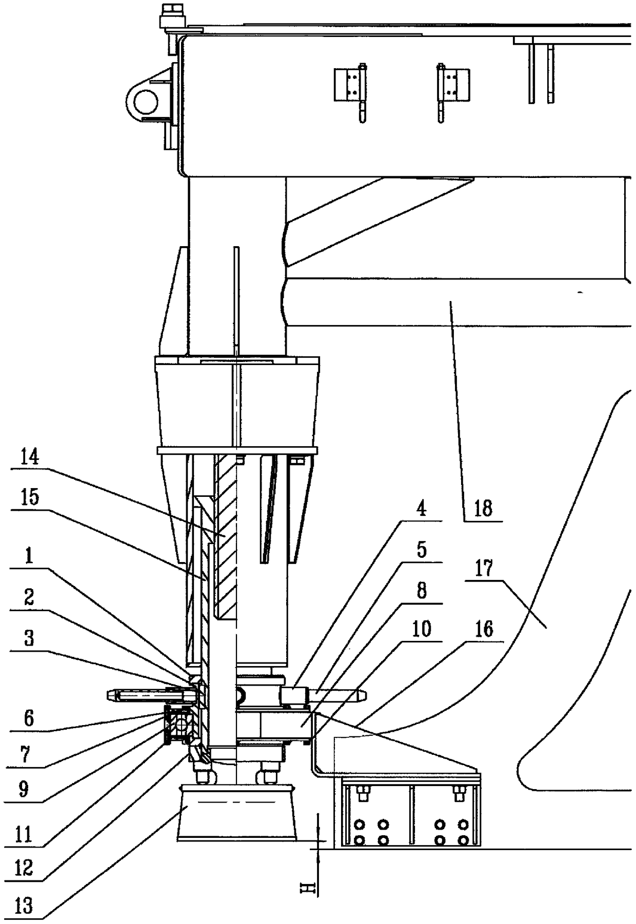
[0016] Such as figure 1 As shown, a launch platform with a deflector that can be lifted is composed of a platform body 18, a deflector 17, 4 sets of adapter frames 16, 4 foot plates 13 and 4 sets of lifting devices. The lifting device includes an end cover 1, Bearing seat 2, key 3, handle seat 4, handle 5, dust-proof ring 6, bearing cover 7, connection plate 8, bearing 9, sealing washer 10, fastener 11, limit ring 12, screw rod 14, standpipe 15. Lifting device is positioned between the support leg of platform body 18 and foot plate 13, and screw mandrel 14 is correspondingly fixedly connected in the center of platform body 18 support legs, and standpipe 15 upper end is threaded with screw mandrel 14, and the lower end welding limit ring 12. The bottom of the l...


PUM


Abstract

The invention provides a launching stand with a lifting deflector. The launching stand with the lifting deflector is formed by a stand body, the deflector, four sets of adapter frames, four foot plates and four sets of lifting devices. The lifting devices are located between support legs of the stand body and the foot plates, and are uniformly distributed on the support legs of the stand body; and each set of lifting device is connected with the deflector through the corresponding adapter frame, so that the deflector can be lifted up and down.

Description

technical field [0001] The invention belongs to the technical field of launch vehicles or missile ground launchers, and in particular relates to a launch platform with a deflector that can be lifted up and down. Background technique [0002] During the launch of carrier rockets or missiles, deflectors are generally used to guide the high-temperature and high-speed gas flow, so as to avoid disorder, backsplash or diffuse gas flow ablation, which will affect the safety of the launch of the missile and arrow, and at the same time cause damage to the key equipment for the launch of the missile and arrow. sexual influence. [0003] At present, at home and abroad, in order to improve the all-weather mobile attack capability of missile launchers, vehicle-mounted launchers are generally used. When the missile is about to be launched, after the launch vehicle erects the missile in place, the impact load of the missile launch gas flow directly acts on the deflector and transmits it t...

Claims


Application Information

Patent Timeline
Patent Type & Authority Patents(China)
IPC IPC(8): F41F3/04F16C35/00
CPCF16C35/00F41F3/0413
Inventor 许成龙杨辉李明兵李放
Owner THE GENERAL DESIGNING INST OF HUBEI SPACE TECH ACAD
Why Eureka
Try Eureka