Coupling braking load limiter

A technology of couplings and load limiters, which is applied in the field of coupling brake load limiters, can solve problems such as machine damage, load limiter single load limiting function, and couplings that cannot be directly applied.

Inactive Publication Date: 2010-08-25
湖北咸宁三合机电股份有限公司
View PDF0 Cites 9 Cited by
  • Summary
  • Abstract
  • Description
  • Claims
  • Application Information

AI Technical Summary

Problems solved by technology

In terms of performance, there are two categories: rigid couplings and flexible couplings. Although both types of couplings can achieve the effect of coupling transmission, when the machine is overloaded, it will not be protected due to overloading. machine, so it is easy to cause damage to the machine, and it will not brake immediately because the machine stops, which will easily cause quality and safety prob

Method used


Image

  • Coupling braking load limiter
  • Coupling braking load limiter
  • Coupling braking load limiter

Examples


Embodiment Construction

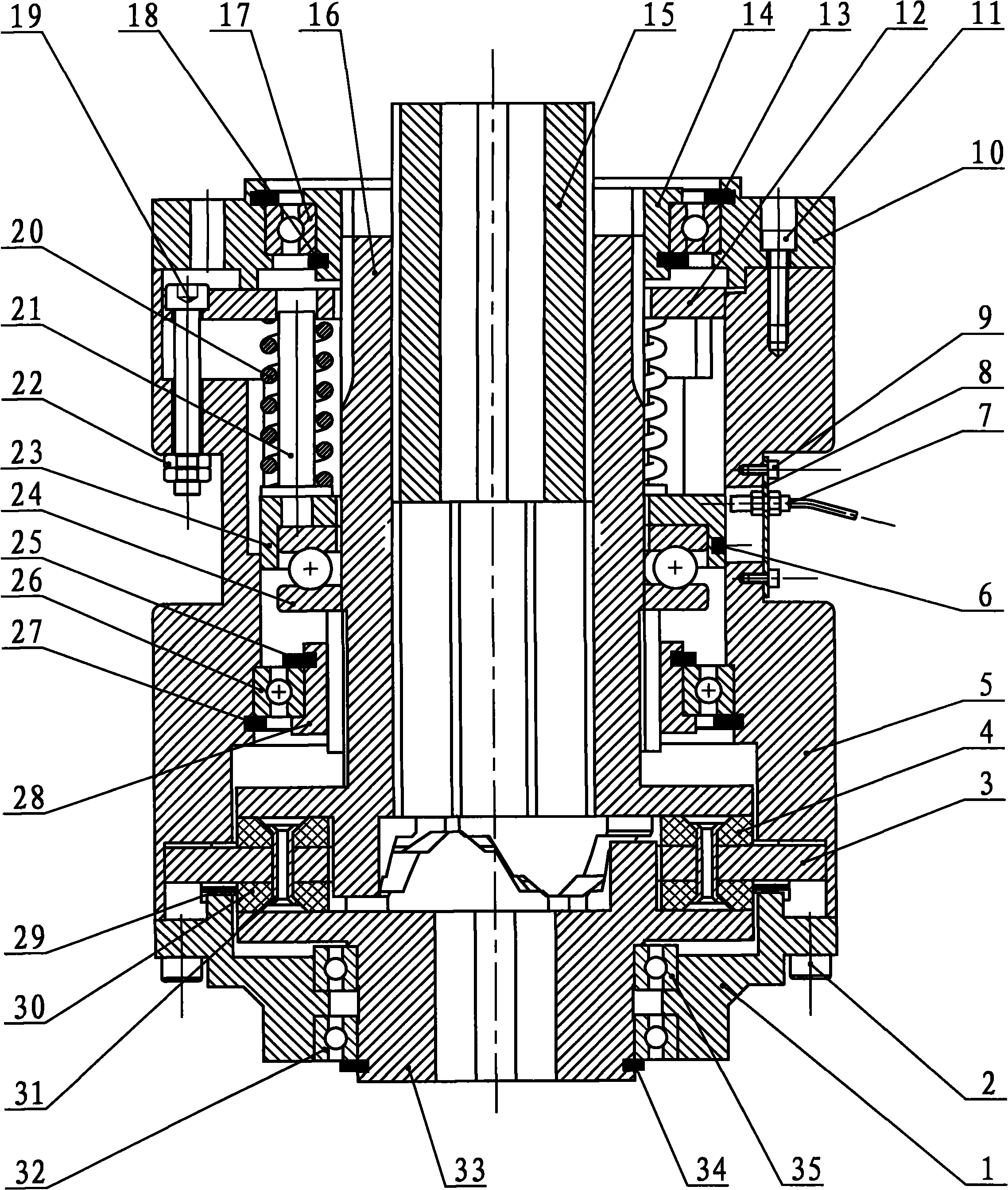
[0022] As shown in Figure 1 in the specification: the rolling bearing 35 and the rolling bearing 32 are connected together with the semi-driven coupling 33 in the form of interference fit, and the circlip 34 for the shaft is stuck in the ring of the shaft end of the semi-driven coupling 33. In the groove, the lower end cover 1 is fixed on the housing 5 with a plurality of hexagon socket head cap screws 2 , and the wave spring 29 is placed on the lower end cover 1 and stuck in the inner ring groove of the housing 5 .

[0023] As shown in Figure 1 in the specification, the friction plate 4 and the friction plate 30 are fixed on the friction plate support 3 by glue joint and riveting of four (or more) copper rivets 31, and the toothed friction plate support 3 is stuck on the shell 5 on several grooves at the lower end.

[0024] As shown in Figure 1 in the specification, the inner hole of the rolling bearing 26 and the outer circle of the lower positioning sleeve 28 are connected ...


PUM


Abstract

The invention discloses a coupling braking load limiter, comprising a case, an upper end cover, an upper locating sleeve assembly, a spring stressed plate, a brake spring assembly, a spring seat, a plane bearing, a lower locating sleeve assembly, a semi-active coupler, a friction plate support assembly and a semi-driven coupler assembly. The coupling braking load limiter is characterized in that the case, the upper end cover, the upper locating sleeve assembly, the spring stressed plate, the brake spring assembly, the spring seat, the plane bearing, the lower locating sleeve assembly, the semi-active coupler, the friction plate support assembly and the semi-driven coupler assembly are arrange in order along the direction of axial line, the semi-active coupler drives an induction magnet to induce a proximity switch during overloading, and then a signal is given out to cut off the power of a main motor, thus realizing the function of an overloading protection working machine. When losing power, the energy stored by pressing the brake spring is released immediately to push the semi-active coupler and the friction plate assembly to generate friction with the semi-driven coupler assembly, thereby forming brake moment and realizing braking. The limiter is widely applied to mechanical transmission.

Description

technical field [0001] The invention relates to a coupling brake load limiter. Background technique [0002] The existing shaft coupling only has the function of shaft coupling, which is a device that connects two shafts or shafts and rotating parts to rotate together without disengagement during the process of transmitting motion and power; the existing brake is used for mechanism or machine deceleration A device that stops or stops, and is sometimes used to adjust or limit the movement speed of a mechanism or machine. It is an important part to ensure the safe and normal operation of a mechanism or machine. In terms of performance, there are two categories: rigid couplings and flexible couplings. Although both types of couplings can achieve the effect of coupling transmission, when the machine is overloaded, it will not be protected due to overloading. machine, so it is easy to cause damage to the machine, and it will not brake immediately because the machine stops, which...

Claims


Application Information

Patent Timeline
IPC IPC(8): F16D67/00
Inventor 万名炎汪作纯
Owner 湖北咸宁三合机电股份有限公司
Why Eureka
Try Eureka