Valve and flow rate regulating device thereof

A technology of flow regulating device and adjusting bolt, which is applied in the direction of valve device, fluid pressure actuating device, valve operation/release device, etc. It can solve the problems of limited application range, difficult realization, complex structure, etc., and achieves convenient operation and easy Realization, strong wild effect

Inactive Publication Date: 2010-08-25
米路加(上海)板金机械技术开发有限公司
View PDF0 Cites 5 Cited by
  • Summary
  • Abstract
  • Description
  • Claims
  • Application Information

AI Technical Summary

Problems solved by technology

However, the design of this damping hole has a fixed size, and the regulation ratio of the flow is fixed, so the scope of application is greatly limited.
In addition, the use of proportional valves to adjust the return flow can also improve the defects of the above-mentioned pressure relief valves, but the cost of using proportional valves is high, the structure is complicated, and it is not easy to implement

Method used


Image

  • Valve and flow rate regulating device thereof
  • Valve and flow rate regulating device thereof
  • Valve and flow rate regulating device thereof

Examples


Embodiment Construction

[0029] The present invention will be further described below in conjunction with accompanying drawing and embodiment:

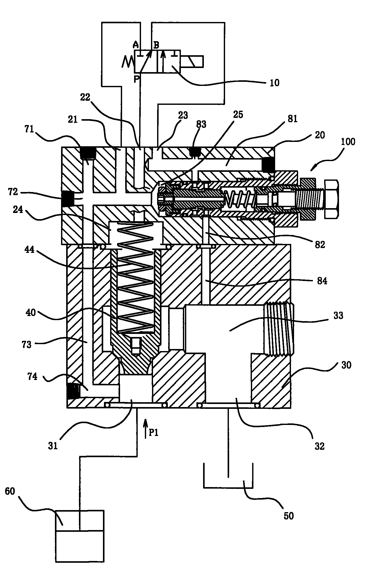
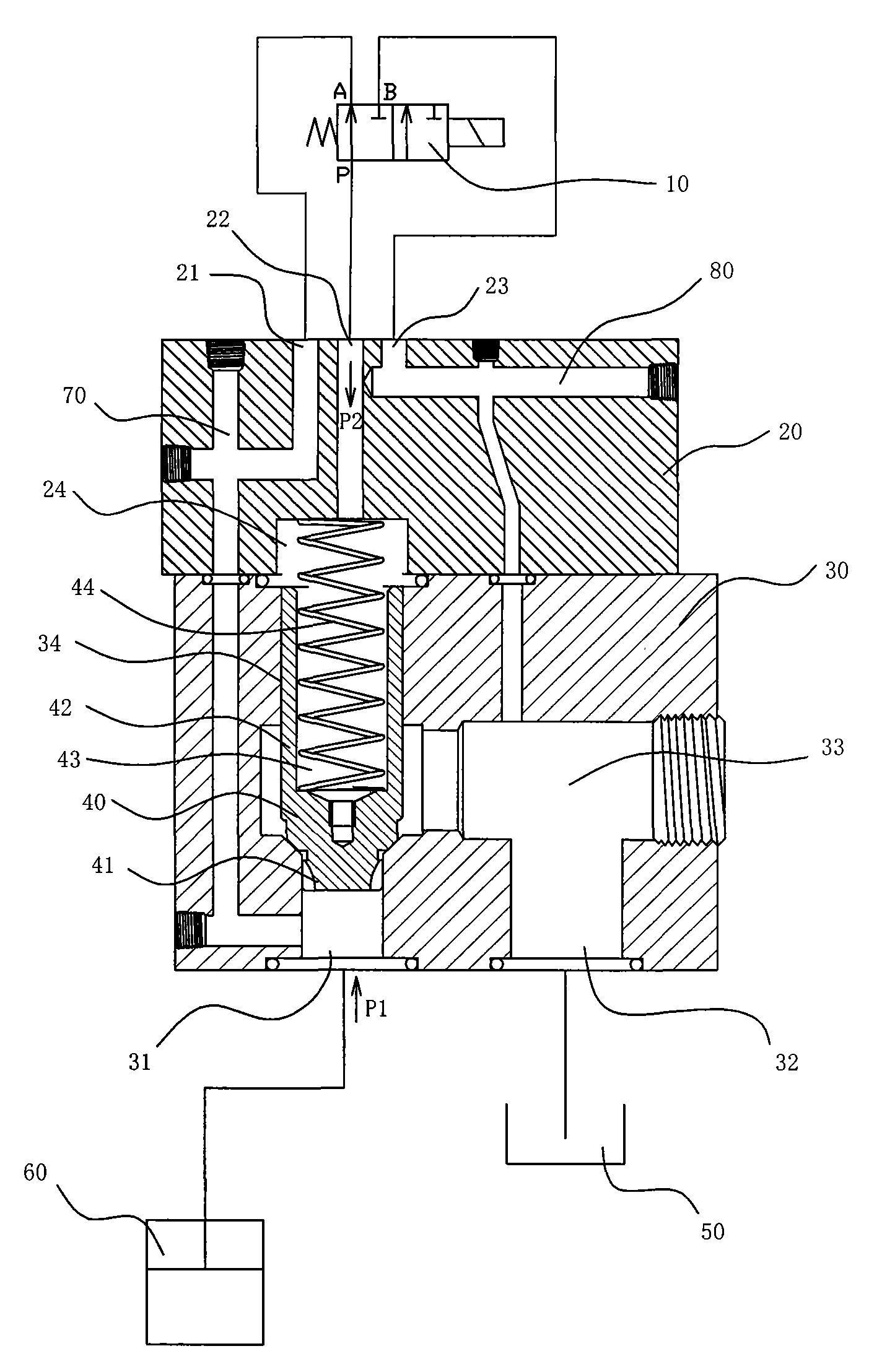
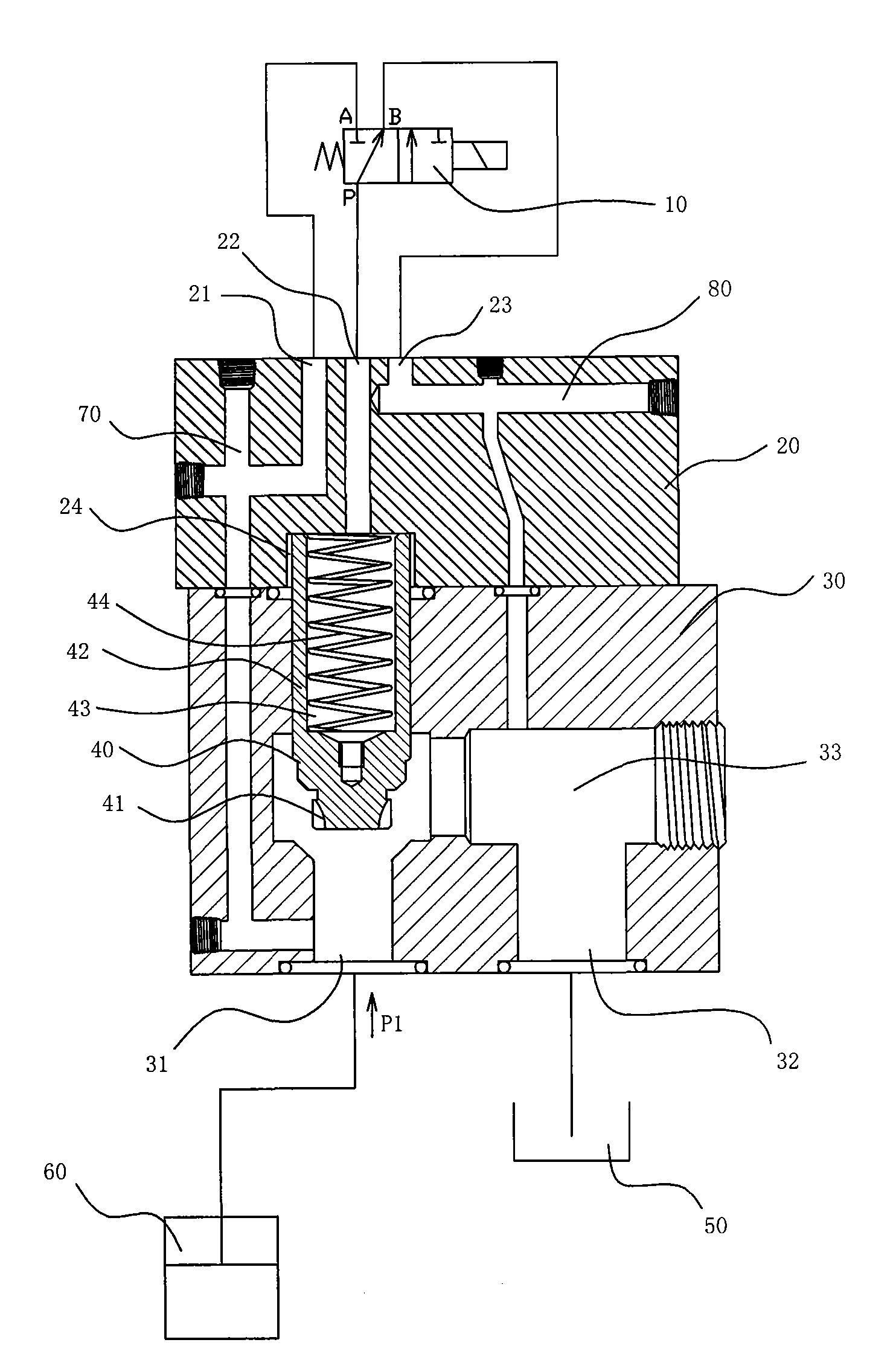
[0030] Fig. 3 and Fig. 4 are respectively a structural sectional view and an exploded view of a pressure relief valve according to an embodiment of the present invention. As shown in the figure, it can be seen that the present invention is a further improvement on the existing pressure relief valve shown in FIG. 1 , and thus has the same main structure as the existing pressure relief valve.

[0031]As shown in FIG. 3 and FIG. 4 , a pressure relief valve according to an embodiment of the present invention includes an upper valve body 20 , a lower valve body 30 , a valve core 40 and a flow adjustment device 100 , and the pressure relief valve is controlled by a solenoid valve 10 . Opening and closing. Specifically, as shown in FIG. 4 , the upper valve body 20 and the lower valve body 30 are locked into one body by a plurality of screws 26 . The lower end of t...


PUM


Abstract

The invention discloses a valve and a flow rate regulating device adopted by the valve. The flow rate regulating device is provided with an input opening and an output opening, wherein a gradually changed V-shaped groove and an annular groove are arranged on a valve rod arranged inside the flow rate regulating device, the gradually changed V-shaped groove changes the communication quantity of the V-shaped groove and the input opening along with the movement of the valve rod, and the annular groove is communicated with the output opening. After the flow rate regulating device is arranged in a valve body through screw thread combination, the input opening is communicated with the back flow hole side of a back flow passage, the output opening is communicated with the output hole side of the back flow passage, and in addition, the axially perforated center hole of the valve rod is communicated with a feed back passage. Through the arrangement of the flow rate regulating device in the back flow passage of the valve, the invention slows down the pressure relief process, so the oil pressure of the input hole is slowly reduced, vibration and noise due to sharp pressure change can not be caused, and the invention provides good shock absorption and nose reduction effect.

Description

technical field [0001] The invention relates to a hydraulic drive system, more specifically, a valve for pressure relief of a hydraulic drive system and a flow regulating device thereof. Background technique [0002] Hydraulic drive is a widely used power source in machining machines. For example, bending machines, stamping machines, etc. often use oil cylinders to drive the action of the upper die, and cooperate with the lower die to bend or stamp products. Hydraulic cylinders are generally connected with booster valves and pressure relief valves. When the booster valve is opened, the hydraulic oil is continuously input into the oil cylinder, so that the hydraulic pressure in the oil cylinder continues to rise, pushing the piston to move downward, and then driving the upper mold to move downward, and the pressure relief valve is closed at this time. After the work is finished, open the pressure relief valve, the hydraulic oil in the oil cylinder will flow back into the oi...

Claims


Application Information

Patent Timeline
IPC IPC(8): F16K1/00F16K31/12F15B15/20
Inventor 川端正晃土山雄司
Owner 米路加(上海)板金机械技术开发有限公司
Why Eureka
Try Eureka