Method for aligning and centering coupler of rotating machinery and special calculator thereof
A technology for rotating machinery and couplings, applied in the field of alignment and alignment of rotating machinery couplings, can solve problems such as inability to fully enter, time-consuming and labor-intensive, difficult to memorize, master, etc., to improve work efficiency and accuracy, and to find The effect is that the process is simple and easy to carry
Inactive Publication Date: 2010-08-25
北京燕化正邦设备检修有限公司
View PDF3 Cites 19 Cited by
- Summary
- Abstract
- Description
- Claims
- Application Information
AI Technical Summary
Problems solved by technology
Its disadvantages are: higher requirements for technicians and certain experience; without mastering the calculation method, relying on experience alone is often time-consuming and labor-intensive, and it is not easy to do it at one time. It usually needs repeated alignment. It is relatively passive to resume production immediately; although the alignment work can be completed more accurately and quickly through the measurement and calculation based on the principle of triangular geometry, the calculation formulas of the four methods of single meter, double meter, three meter and multi meter are cumbersome and different. The same, it is difficult to memorize and master; sometimes it is necessary to make special racks according to the environment and working conditions
Although the laser alignment method is advanced, there are also disadvantages: First, the price of the laser alignment instrument is relatively high. Although it has dropped from more than 200,000 yuan at the beginning to 70,000 to 80,000 yuan now, it still cannot fully enter the grassroots application of various industrial enterprises; Secondly, high-speed machines generally use sliding bearings. Due to the positioning method of the sliding bearings and the rotor, there is an axial gap between the rotor and the stator. The laser alignment instrument cannot eliminate the influence of the axial displacement of the rotor on the angle deviation. The dial indicator method such as three-meter or multi-meter alignment method must be used; in addition, in the mechanical equipment that does not allow the rotor to rotate or the rotor with a special-shaped coupling, such as a centrifugal compressor with a dry gas seal, the rotor is not allowed to rotate. , the laser alignment instrument cannot meet the requirements for installation and maintenance, and a more flexible dial indicator alignment method is needed at this time
To sum up, among the two commonly used alignment methods at present, the dial indicator alignment method is low in cost and wide in applicability, but the calculation method is difficult to master, time-consuming and laborious
The laser alignment method is simple and fast, which can greatly improve work efficiency and accuracy. The method is advanced, but the laser alignment instrument is expensive and has certain limitations in use.
Method used
View moreImage
Smart ImageViewing Examples
Examples
Embodiment Construction
Login to View More PUM
 Abstract
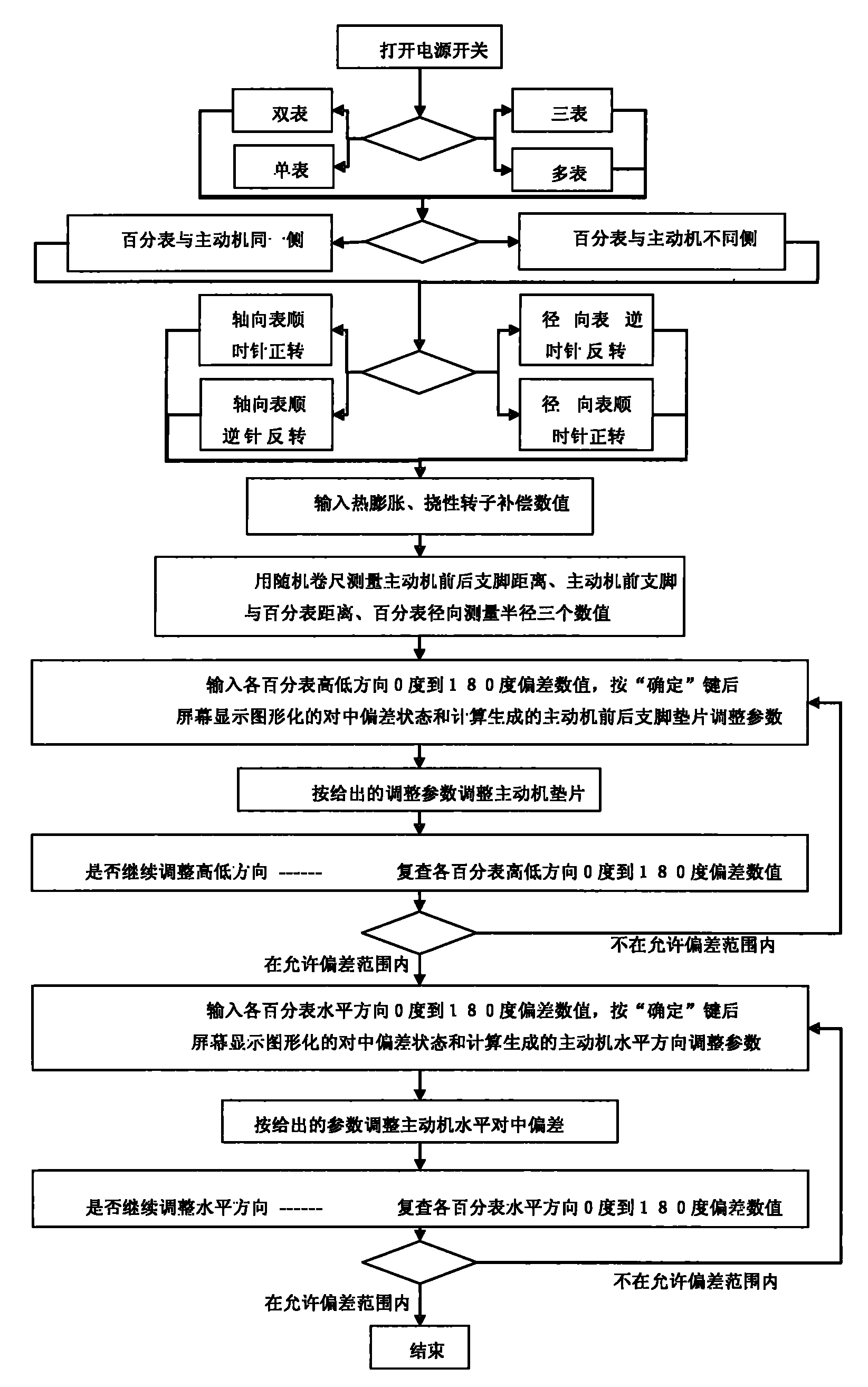
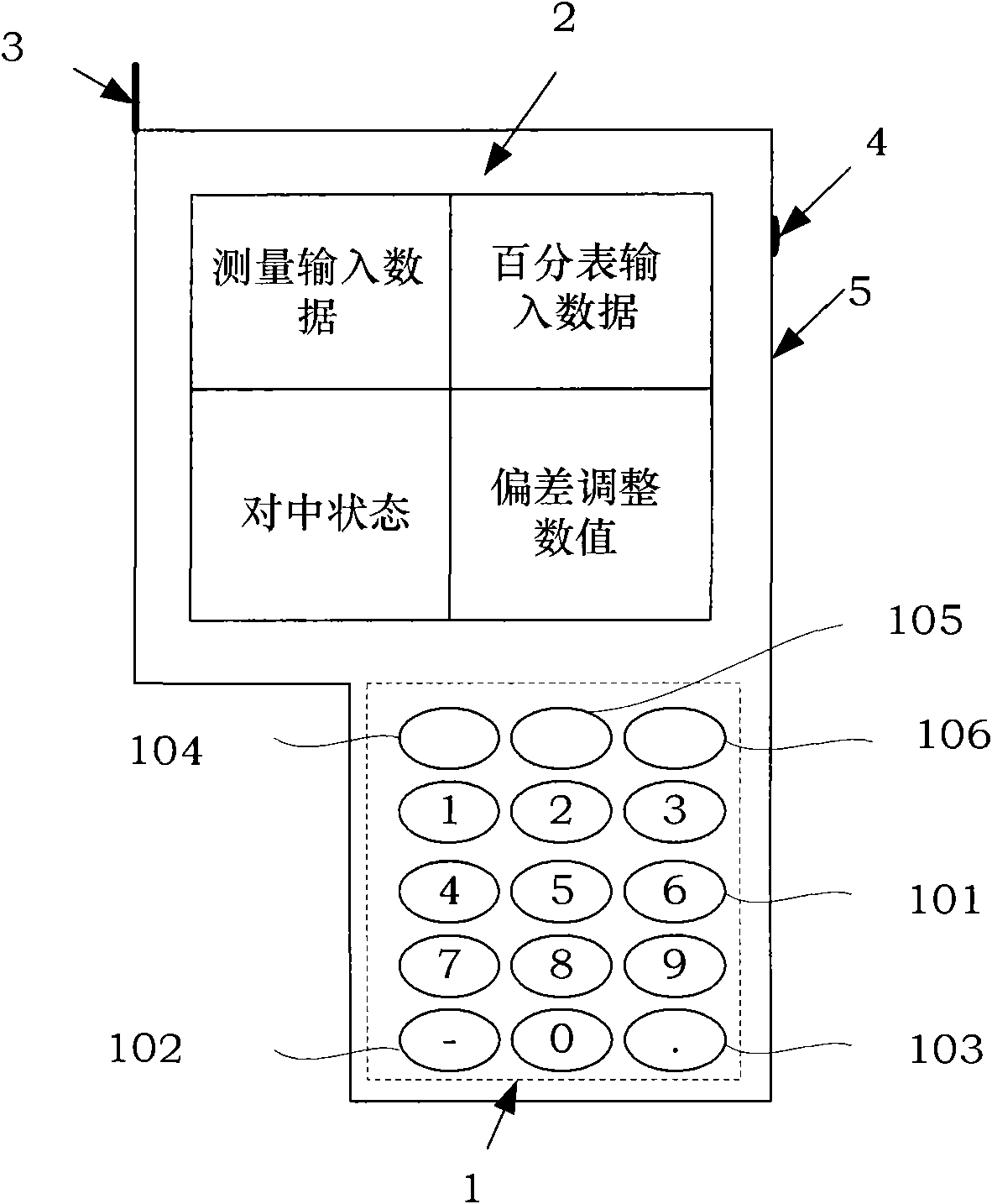
The invention discloses a method for aligning and centering a coupler of rotating machinery and a special calculator thereof, and is applied to occasions needing alignment during arranging or maintaining the rotating machinery. By combining a dial gauge and a gauge frame, or during the use of a dial gauge type aligning and centering instrument, the aligning and centering work can be rapidly and accurately finished. Several necessary dimension parameters and the indication of the dial gauge are only needed to be measured; the patterned working process is selected according to an internal procedure; and an aligning and centering adjustment value is generated by calculating according to the internal procedure in the device, and the aligning and centering adjustment is performed. Therefore, the aligning and centering work can be conveniently and rapidly finished. The method for aligning and centering the coupler of the rotating machinery and the special calculator thereof have the advantages that: the aligning and centering work of the rotating machinery is performed without tedious calculation or graphical method, and particularly the aligning and centering process evaluated and repeatedly adjusted by experiences is not needed. Therefore, the method is simple, easy to master, time-saving and labor-saving, can lighten the labor intensity and has more visualized determined value. Compared with a laser alignment instrument, the method has the characteristics of wide applicability, low cost, and portability.
Description
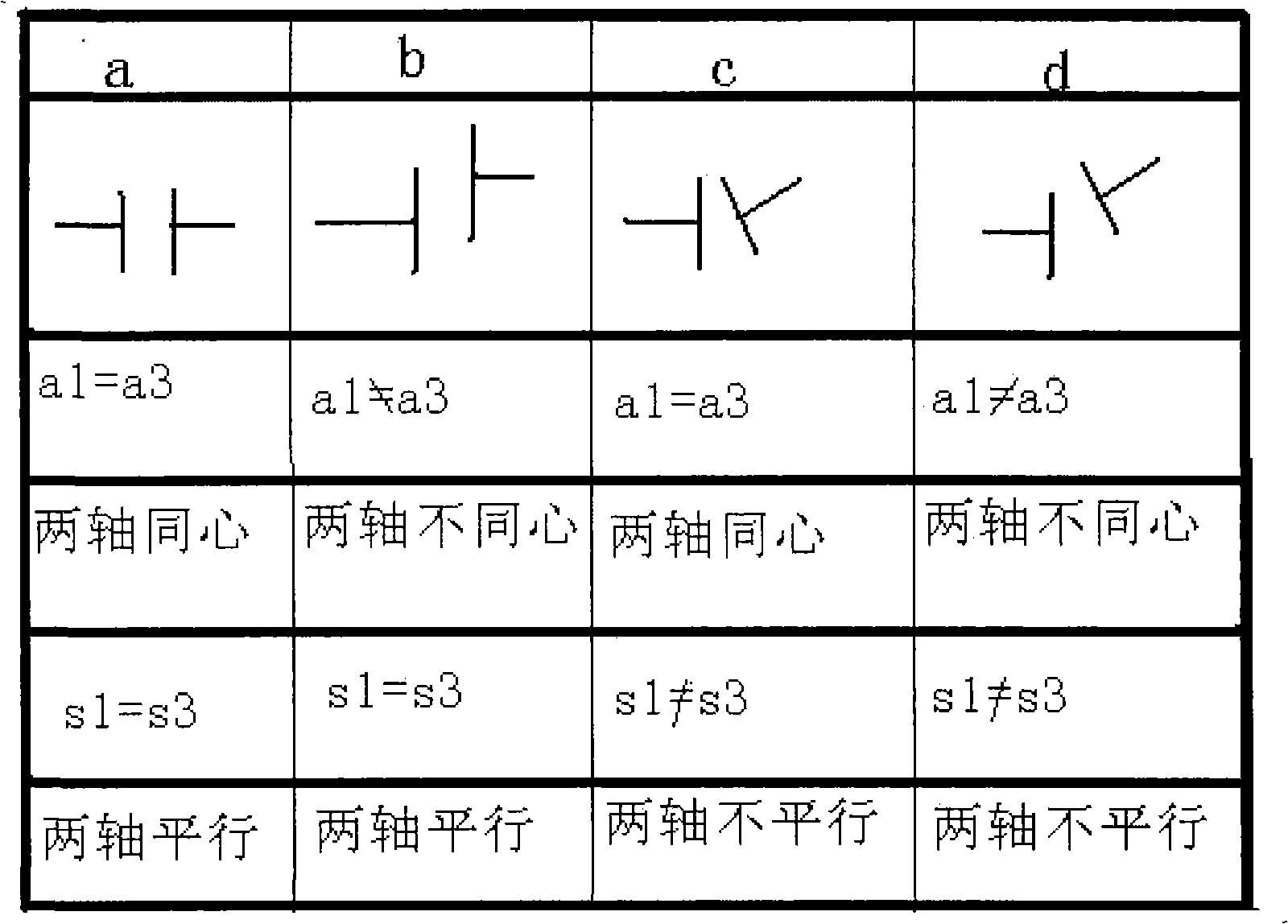
technical field The invention relates to the technical field of installation of rotating machinery equipment and inspection and maintenance of rotating machinery equipment, in particular to a method and device for alignment and centering of a rotating machinery coupling. Background technique Rotating machinery is the most widely used mechanical equipment in industry. Many large rotating machinery, such as: centrifugal pumps, generators, compressors, steam turbines, rolling mills, rotary kilns, etc., are key equipment for industrial enterprises. Among the faults of rotating machinery, 60% of shafting faults are caused by misalignment of the rotor, and various forms of misalignment are shown in Attached Table 1: Table 1 Various forms of misalignment The misalignment state of this rotor-bearing-coupling system in actual engineering is very common. Due to the misalignment of the rotor, it causes vibration and noise during the operation of the rotating machine, and at the sa...
Claims
Login to View More Application Information
Patent Timeline
 IPC IPC(8): G01B5/00G06F15/02
Inventor 张亚光
Owner 北京燕化正邦设备检修有限公司
Features
- R&D
- Intellectual Property
- Life Sciences
- Materials
- Tech Scout
- Unparalleled Data Quality
- Higher Quality Content
- 60% Fewer Hallucinations
Learn More Browse by: Latest US Patents, China's latest patents, Technical Efficacy Thesaurus, Application Domain, Technology Topic, Popular Technical Reports.
© 2025 PatSnap. All rights reserved.Legal|Privacy policy|Modern Slavery Act Transparency Statement|Sitemap|About US| Contact US: help@patsnap.com


