Temperature-compensated optical fiber sagnac interference ring strain sensor
A strain sensor and temperature compensation technology, applied in the direction of instruments, optical devices, measuring devices, etc., can solve the problems of expensive equipment, high cost, complex system, etc., and achieve the effect of low cost, small size and high sensitivity
Inactive Publication Date: 2010-08-25
SHANGHAI JIAO TONG UNIV +1
View PDF6 Cites 17 Cited by
- Summary
- Abstract
- Description
- Claims
- Application Information
AI Technical Summary
Problems solved by technology
However, the preparation of PCFLPG used in this technology
Method used
View moreImage
Smart ImageViewing Examples

Examples
Embodiment
Login to view more PUM
| Property | Measurement | Unit |
|---|---|---|
| Bandwidth | aaaaa | aaaaa |
| Diameter | aaaaa | aaaaa |
Abstract
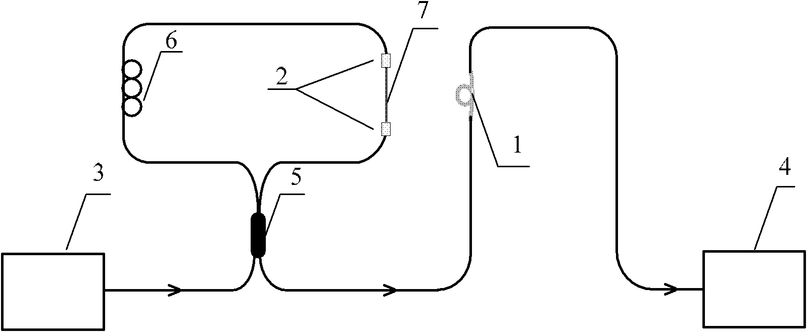
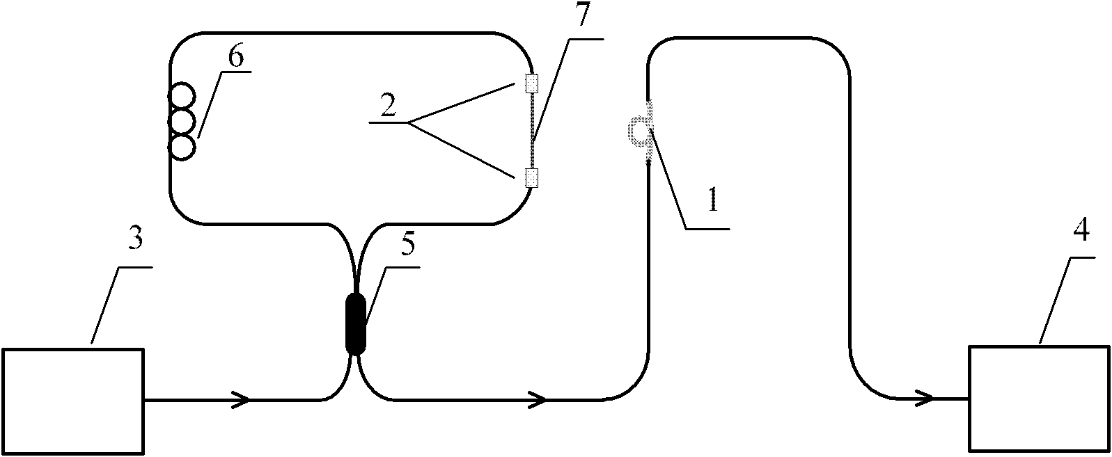
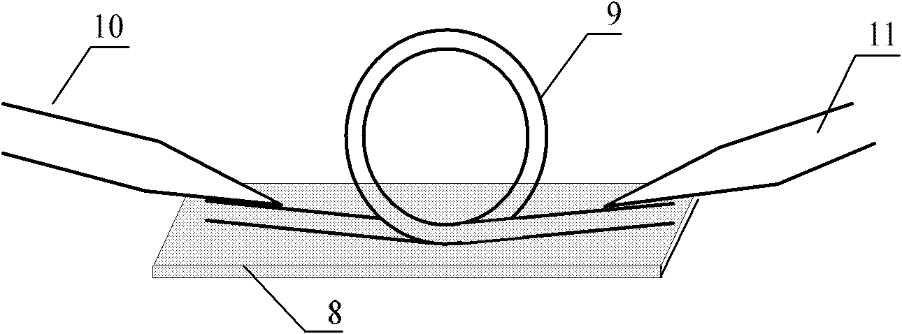
The invention relates to a temperature-compensated optical fiber sagnac interference ring strain sensor in the technical field of optical fiber sensing, which comprises an Hi-Bi sagnac interference ring, an optical fiber micro-ring resonator, an optical precision displacement platform, a light source and a spectrum analyzer, wherein the light source is connected with the optical fiber micro-ring resonator, the Hi-Bi sagnac interference ring is connected with the optical fiber micro-ring resonator, the optical fiber micro-ring resonator is connected with the spectrum analyzer, and the Hi-Bi sagnac interference ring is arranged on the optical precision displacement platform; the Hi-Bi sagnac interference ring comprises a coupler, a polarization controller and a birefringent optical fiber, wherein the birefringent optical fiber is used as a sensing arm and simultaneously placed in a temperature field and a strain field; and the optical fiber micro-ring resonator comprises a substrate and a polymer optical fiber ring, wherein the polymer optical fiber ring is only placed in the temperature field for temperature compensation. The invention effectively solves the cross sensitivity problem of the temperature and the strain and has small size, simple structure, low cost and high measuring sensitivity.
Description
Optical fiber sagnac interference ring strain sensor with temperature compensation technical field The invention relates to a device in the technical field of optical fiber sensing, in particular to an optical fiber high birefringence sagnac interference ring (Highbirefringentsagnacloop, Hi-Bisagnacloop, high birefringence Sagnac interference ring) strain sensor with temperature compensation. Background technique In recent years, the application of optical fiber sagnac interference rings in sensing has attracted more and more attention. In the optical fiber sagnac interference ring sensing scheme, the high birefringence optical fiber sagnac ring has great application prospects in the field of optical fiber sensing. Hi-Bisagnac (high birefringence Sagnac) interference ring is a series of high birefringence fiber in the basic sagnac ring, the output spectrum presents periodic filtering characteristics, and the period of the output spectrum is determined by the Hi-Bi in the r...
Claims
Login to view more Application Information
Patent Timeline
 IPC IPC(8): G01B11/16
Inventor 史杰肖石林陈荷朱敏毕美华
Owner SHANGHAI JIAO TONG UNIV
- R&D Engineer
- R&D Manager
- IP Professional
Why Eureka
- Industry Leading Data Capabilities
- Powerful AI technology
- Patent DNA Extraction
Try Eureka
Browse by: Latest US Patents, China's latest patents, Technical Efficacy Thesaurus, Application Domain, Technology Topic.
© 2024 PatSnap. All rights reserved.Legal|Privacy policy|Modern Slavery Act Transparency Statement|Sitemap