Charge and discharge test equipment for full on-line storage battery pack

A charging and discharging test, battery pack technology, applied in the direction of measuring electricity, measuring devices, measuring electrical variables, etc., can solve the problems of interruption accident, high risk, waste of energy, etc., to achieve flexible and safe use, wide range of use, and degree of intelligence high effect

CN101813755BActive Publication Date: 2013-06-19FUZHOU FUGUANG ELECTRONICS +1
6 Cites 1 Cited by

Patent Information

Authority / Receiving Office
CN · China
Patent Type
Patents(China)
Current Assignee / Owner
Publication Date
2013-06-19

Smart Images

  • Figure 1
    Figure 1
  • Figure 2
    Figure 2
Patent Text Reader

Abstract

The invention provides a charge and discharge test equipment for a full on-line storage battery pack, which comprises a DC-DC host operating power supply, a control unit, a positive and negative polarity change-over switch, a second safeguard circuit, a safeguard circuit, an automatic current limiting charge and equipotential bonding safety control circuit, a DC-DC transducer, a constant current discharge load intelligent control circuit and a discharge load circuit, wherein the safeguard circuit, the automatic current limiting charge and equipotential bonding safety control circuit and the DC-DC transducer are mutually connected in parallel; and the constant current discharge load intelligent control circuit and the discharge load circuit are mutually connected in series. The equipment realizes the best safe operation mode and is suitable for charge and discharge maintenance tests of the on-line storage battery packs of different positive and negative communication power supplies. Nomatter the operating power supply is positively grounded or negatively grounded, when the equipment carries out on-line maintenance test, only the power supply operating grounding terminal connected with side of the storage battery pack needs to be operated, thereby avoiding the risk of short circuit caused by contacting the ground in operation, and the equipment has the charge and discharge maintenance functions of constant current voltage limiting and voltage stabilized current limiting for the on-line storage battery packs, and is more flexible, safer and simpler in use of maintenance test.
Need to check novelty before this filing date? Find Prior Art

Description

Technical field

[0001] The invention relates to power supply maintenance equipment in a communication network, in particular to an all-on-line charging and discharging test equipment for battery packs.

Background technique

[0002] The existing wireless base station power backup battery maintenance and management in the communication industry, due to the large number of wireless base stations, high maintenance labor intensity, high cost, high risk, heavy maintenance tasks, and waste of energy, most of the battery capacity discharge test The maintenance work has not been implemented in place, resulting in the ignorance of the actual capacity of the backup battery pack of the wireless communication base station, the duration of emergency power supply is not clear, and the emergency power generation dispatch management cannot be effectively carried out due to the interruption of the mains power supply, which often leads to communication interruption accidents of the wireless...

Examples

Embodiment 1

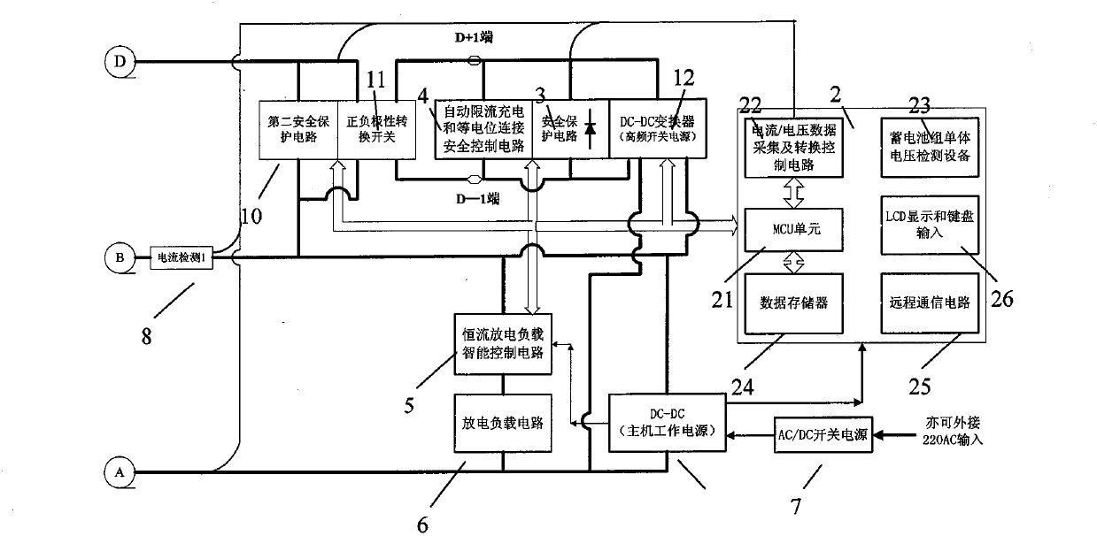
[0040] see figure 1 As shown, the full-line battery charge and discharge test equipment of this embodiment includes a DC-DC host power supply 1, a control unit 2, a safety protection circuit 3, and an automatic current-limiting charging and equipotential bonding safety control circuit 4 , a constant current discharge load intelligent control circuit 5, a discharge load circuit 6, a DC-DC converter 12, a positive and negative polarity conversion switch 11, a second safety protection circuit 10 and other circuit modules. The control unit 2 further includes an MCU unit 21, and a current / voltage data acquisition and conversion control circuit 22 connected to the MCU unit 21, a battery unit voltage detection device 23, a data memory 24, and a remote communication circuit. 25. LCD display and keyboard input 26.

[0041] The safety protection circuit 3 , the automatic current limiting charging and equipotential connection safety control circuit 4 , and the DC-DC converter 12 are con...

Embodiment 2

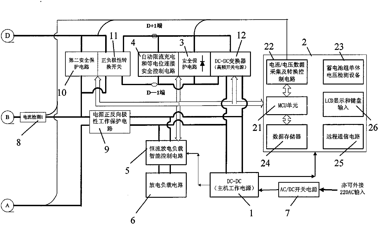
[0060] see figure 2 Compared with Embodiment 1, the difference between the second embodiment and the first embodiment is that the full-on-line storage battery charge and discharge test equipment in the second embodiment also includes a power supply forward and reverse polarity protection circuit 9, and the forward and reverse polarity of the power supply The output of the polarity work protection circuit 9 is connected in series with the constant current discharge load intelligent control circuit 5 and the discharge load circuit 6, and then connected in series to the DC-DC converter 12 and the DC-DC host operating power supply 1 connected in parallel. All the other structures are the same as in Embodiment 1.

[0061] Explanation: In the first embodiment, the DC-DC converter 12, the constant current discharge load intelligent control circuit 5, and the DC-DC host operating power supply 1 are distributed in the forward and reverse polarity protection circuit function of the inp...