LED lamp control circuit and LED lamp

A technology of LED lamps and control circuits, which is applied in the field of lighting, can solve the problems of small output constant current range of constant current chip, narrow input voltage range of constant current chip, and inability to meet a large range of voltage input, etc., to achieve good compatibility, The effect of high flexibility

Active Publication Date: 2010-08-25
OCEANS KING LIGHTING SCI&TECH CO LTD +1
View PDF3 Cites 16 Cited by
  • Summary
  • Abstract
  • Description
  • Claims
  • Application Information

AI Technical Summary

Problems solved by technology

Existing LED lighting control circuits mainly use constant current chips to achieve constant current drive. Since the input voltage range of the constant current chip is narrow, it will not be able to meet a wide range of voltage input, and the output constant current range of the constant current chip is small.

Method used


Image

  • LED lamp control circuit and LED lamp
  • LED lamp control circuit and LED lamp
  • LED lamp control circuit and LED lamp

Examples


Embodiment Construction

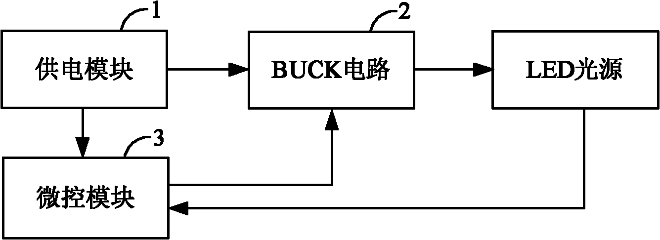
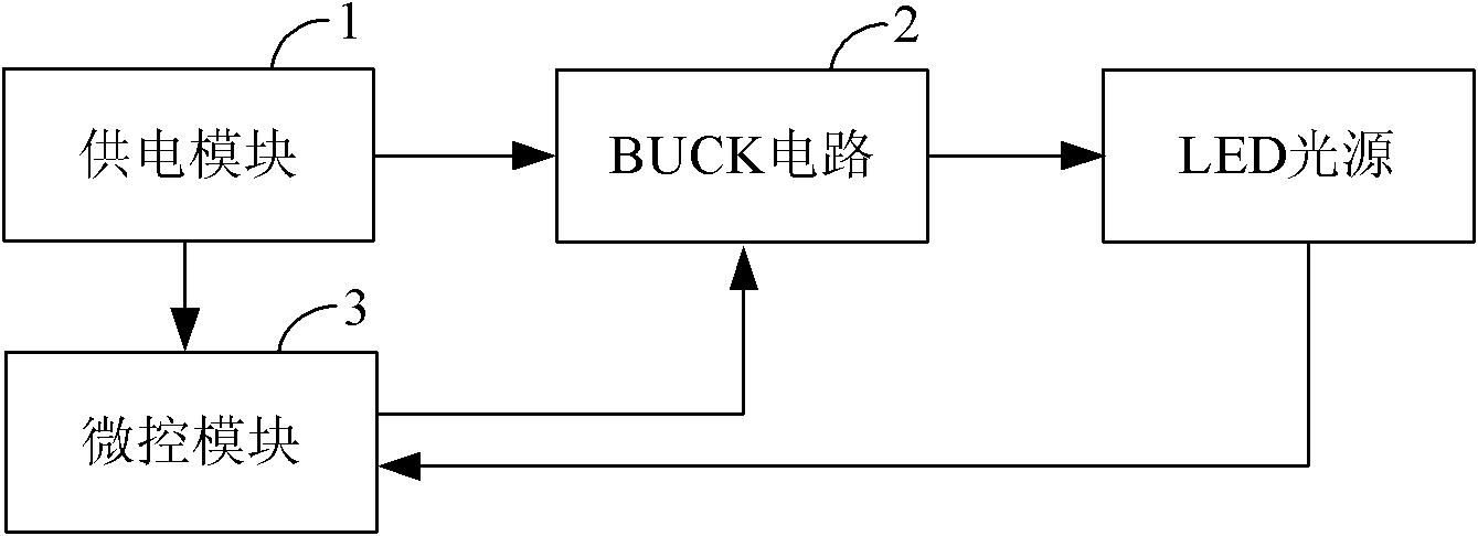
[0030] As shown in FIG. 1 , it is a functional block diagram of the first embodiment of the LED lamp control circuit of the present invention. The LED lamp control circuit of the present invention is connected with the LED light source, and it includes a power supply module 1, a BUCK circuit 2 and a micro control module 3, the power supply module 1 is connected with the BUCK circuit 2 and the micro control module 3 respectively, and the BUCK circuit 2 is connected with the micro control module 3 are connected, the power supply module 1 supplies power to the BUCK circuit 2 and the micro-control module 3, the micro-control module 3 generates a square wave signal according to the working current of the LED light source, and the BUCK circuit 2 generates a constant DC voltage according to the square wave signal to drive the LED The light source glows. In the present invention, the BUCK circuit 2 is used to generate the constant DC voltage, which has the characteristics of a wide in...


PUM


Abstract

The invention relates to an LED lamp control circuit and an LED lamp which are connected with an LED light source. The LED lamp control circuit comprises a power supply module, a BUCK circuit and a micro-control module, wherein the power supply module supplies power for the micro-control module and the BUCK circuit; the micro-control module generates a square wave signal according to the operating current of the LED light source; and the BUCK circuit generates a constant DC voltage so as to drive the LED light source to illuminate. In the invention, the BUCK circuit is used for generating the constant DC voltage and has the characteristics of wide input voltage range and large output constant current. Moreover, when the input voltage of the power supply module or the parameters of the LED light source change, the magnitude of the finally generated constant DC voltage can be adjusted by adjusting the parameters of components in the BUCK circuit. The invention has high flexibility and good compatibility.

Description

technical field [0001] The invention relates to the technical field of lighting, and more specifically, to an LED lamp control circuit and an LED lamp. Background technique [0002] In the prior art, the LED light source has the advantages of high efficiency and energy saving, long life, low voltage controllability, etc., so it is widely used in various lamps. Existing LED lighting control circuits mainly use constant current chips to achieve constant current driving. Since the input voltage range of the constant current chip is narrow, it will not be able to meet a wide range of voltage input, and the output constant current range of the constant current chip is small. Therefore, there is an urgent need for an LED lamp control circuit and an LED lamp with a wider input voltage range and a larger output constant current range. Contents of the invention [0003] The technical problem to be solved by the present invention is to provide a device that satisfies the input volt...

Claims


Application Information

Patent Timeline
Patent Type & Authority Applications(China)
IPC IPC(8): H05B37/02F21S2/00F21V23/00F21Y101/02
Inventor 周明杰胡启
Owner OCEANS KING LIGHTING SCI&TECH CO LTD
Why Eureka
Try Eureka