Pallet transfer equipment

A pallet conveying and pallet technology, used in conveyors, mechanical conveyors, railway systems with propulsion equipment, etc., can solve the problem that the installation space of processing equipment is limited between the return line and the transmission line, and there is no space saving and installation space. Restricted and other problems, to achieve the effect of easy and accurate vertical positioning, space saving, and ensuring the working space

Inactive Publication Date: 2010-08-25
DAIHATSU MOTOR CO LTD
View PDF2 Cites 2 Cited by
  • Summary
  • Abstract
  • Description
  • Claims
  • Application Information

AI Technical Summary

Problems solved by technology

[0006] However, the conveying lines disclosed in Patent Documents 1 and 2 are all conveying lines that are circulated by the return line and the conveying line. As a result, the installation space for processing equipment and the like is limited to between the return line and the conveying line.
In this case, the installation space is limited, and as a result, the available processing equipment and the like are limited.
Furthermore, the methods disclosed in Patent Documents 1 and 2 are the same in that they require ample space for the loopback line, and there is no fundamental measure for space saving.

Method used


Image

  • Pallet transfer equipment
  • Pallet transfer equipment
  • Pallet transfer equipment

Examples


Embodiment Construction

[0071] Hereinafter, one Embodiment of the tray conveyance facility of this invention is demonstrated based on drawing.

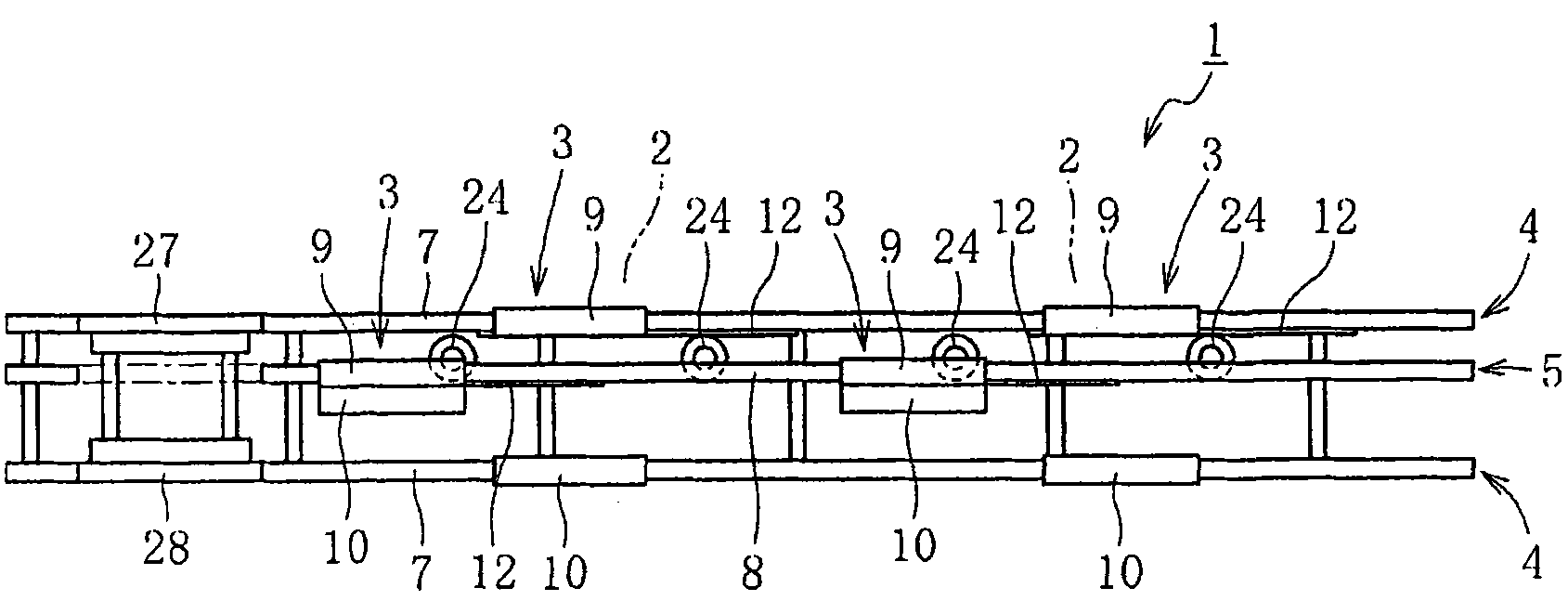
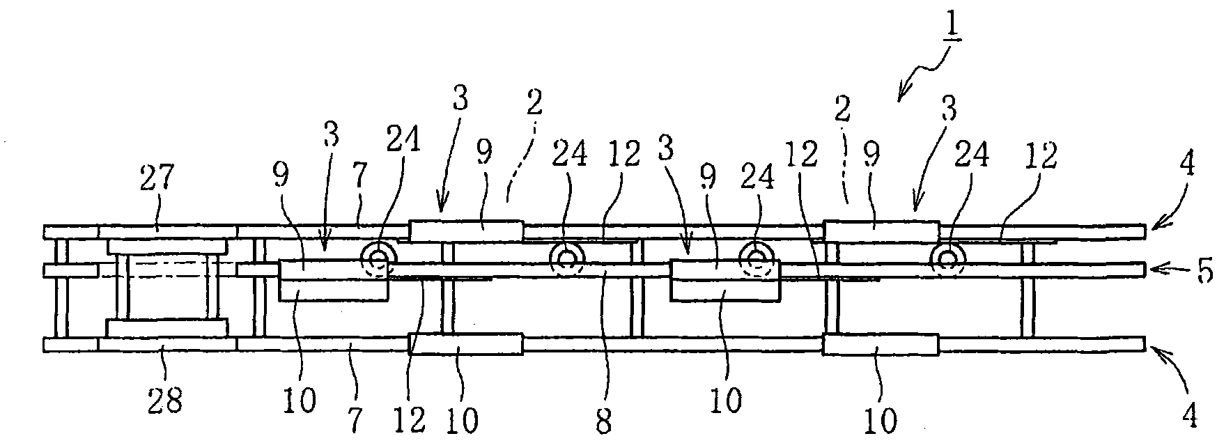
[0072] FIG. 1 is a plan view of a part of a tray conveyance facility according to one embodiment of the present invention. As shown in the figure, this conveying equipment 1 is a part incorporated into a line for conveying a vehicle body 2 as a workpiece, and has a conveying line 4 for conveying a pallet 3 on which a vehicle body 2 is placed (here, a workpiece conveying with pallets); a return line 5 which returns empty pallets 3 from the end of the transfer line 4 .

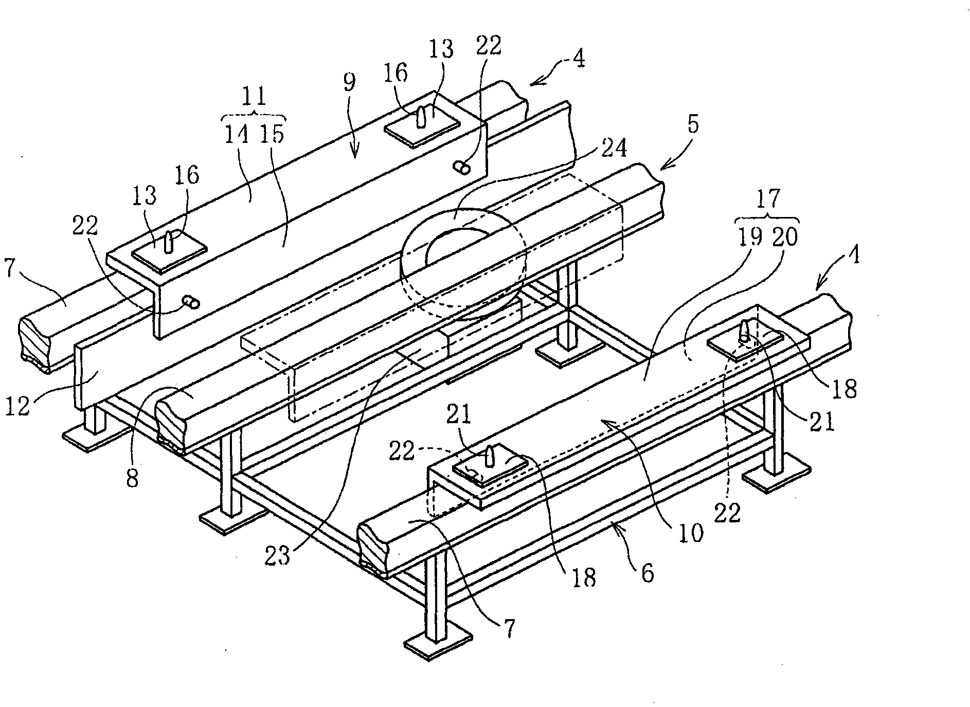
[0073] Here, the transmission lines 4 are arranged in two rows parallel to each other. In this embodiment, as shown in FIG. 2 , each transmission line 4 is constituted by a transmission rail 7 arranged on a frame 6 as a base. Furthermore, the loopback line 5 is arranged between two parallel transmission lines 4 , and is constituted by loopback rails 8 arranged on the frame 6 as a base, simil...


PUM


Abstract

A working space for works and an equipment space for equipment required for working are ensured by saving a space required for pallet transfer equipment. Pallet transfer equipment (1) is provided with two delivery lines (4) for delivering a pallet (3) whereupon a vehicle (2) is mounted as a work; and a returning line (5) for returning the empty pallet (3) from the end to the start of the delivery lines (4). On the delivery lines (4) arranged in parallel, right and left separated pallets (9, 10) are arranged, respectively. The returning line (5) is arranged between a pair of delivery lines (4, 4). The pair of separated pallets (9, 10) are delivered over the corresponding delivery lines (4, 4), and the separated pallets (9, 10) are returned over the returning line (5) in a combined state.

Description

technical field [0001] The present invention relates to pallet conveying equipment. Background technique [0002] Various methods have been proposed and implemented for conveying equipment for pallets for conveying workpieces. For example, conveying equipment for conveying pallets such as vehicle bodies and body parts has been proposed from the viewpoint of conveying efficiency and space saving as follows. [0003] For example, in JP-A-2006-44810 (Patent Document 1), for the purpose of realizing space-saving of the return line, a tray transport line is disclosed, which has: a transport line for transporting trays in a horizontal state, The tray mounts and conveys automotive glass as a workpiece, and the return line supports and returns the tray in a vertical state from the terminal end of the conveyance line toward the beginning end. [0004] In addition, Japanese Patent Application Laid-Open No. 9-142643 (Patent Document 2) discloses a method in which a car storage facilit...

Claims


Application Information

Patent Timeline
Patent Type & Authority Applications(China)
IPC IPC(8): B65G35/06B61B13/12B65G37/00
CPCB61B13/12
Inventor 喜夛功池田和人草部孝行大岛浩充武内浩昭那须信夫泉谷卓司高桥幸一
Owner DAIHATSU MOTOR CO LTD
Why Eureka
Try Eureka