Low-pressure glue-injection machine
A glue injection machine, low pressure technology, applied in the direction of coating, the device for coating liquid on the surface, etc., can solve the problems of easy damage and easy blockage of the hose, and achieve the effect of ensuring normal use, reducing energy consumption and reducing resistance.
- Summary
- Abstract
- Description
- Claims
- Application Information
AI Technical Summary
Problems solved by technology
Method used
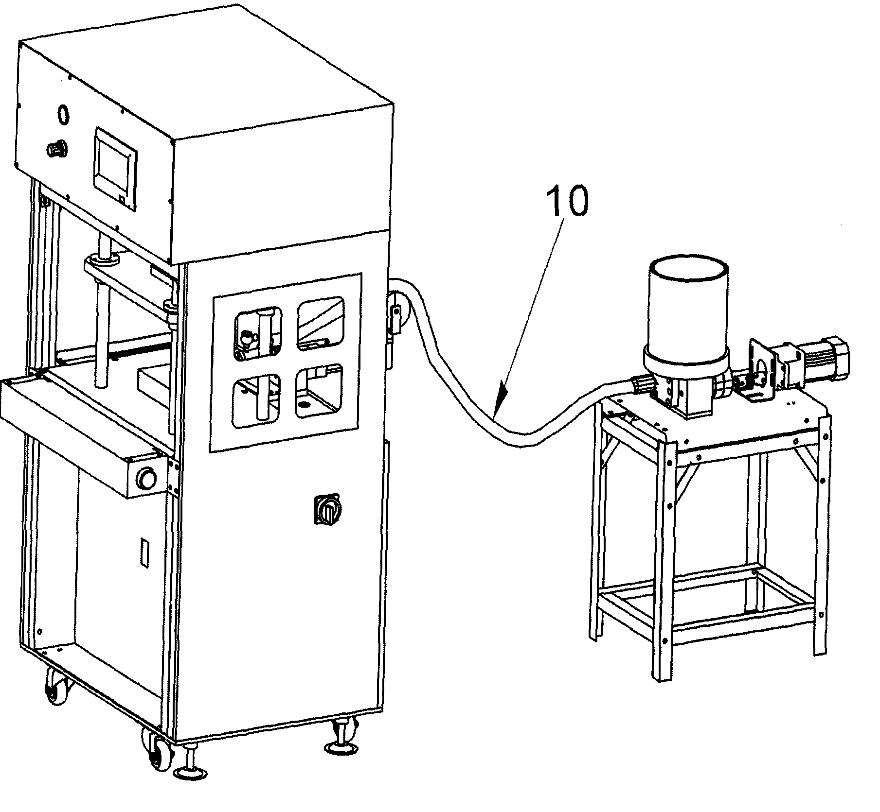
Image

Examples
Embodiment Construction
[0028] A specific embodiment of the present invention will be described in detail below in conjunction with the accompanying drawings, but it should be understood that the protection scope of the present invention is not limited by the specific embodiment.
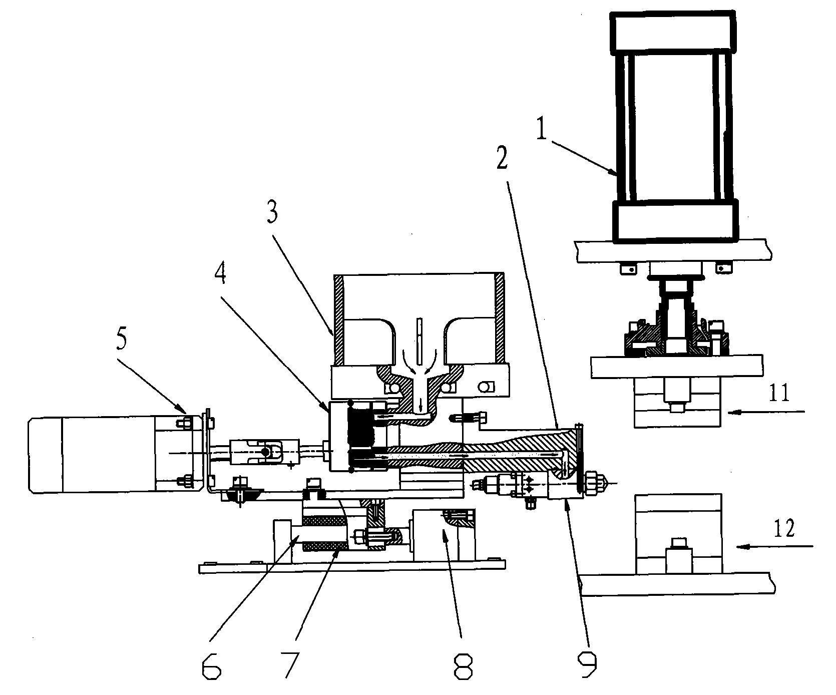
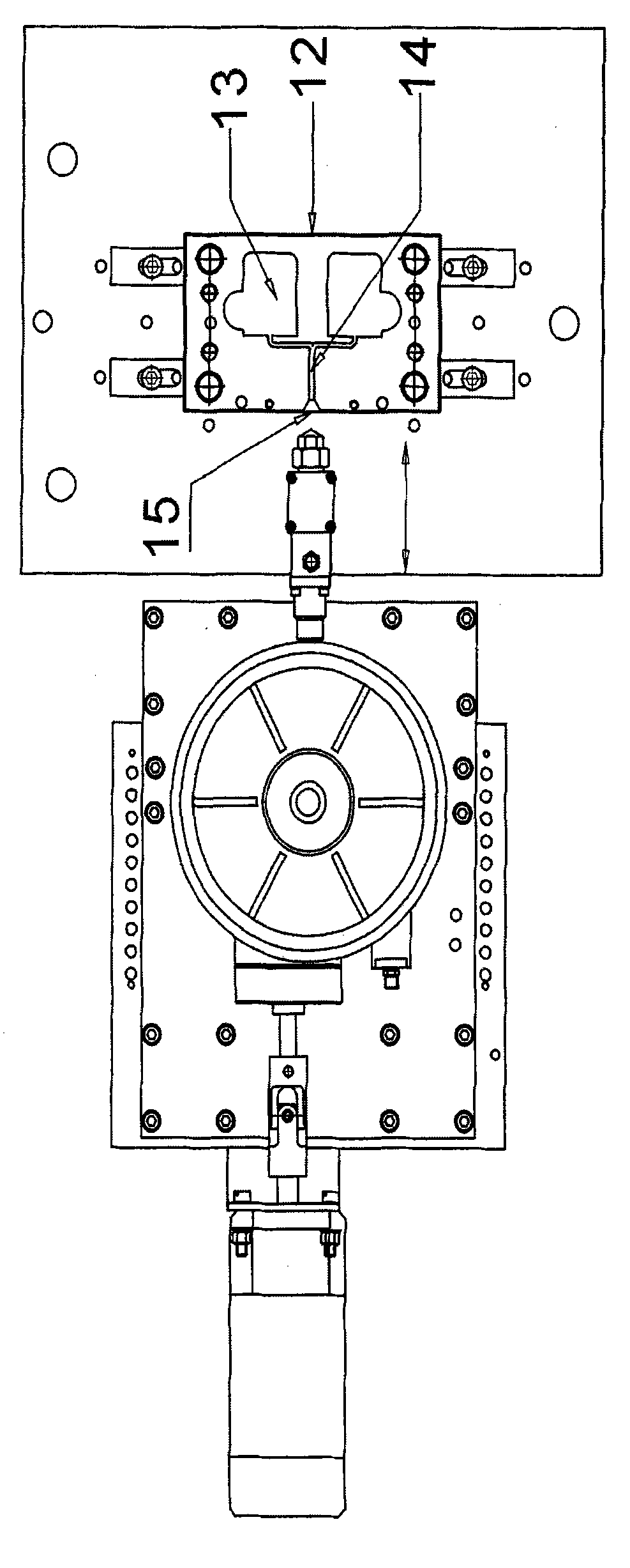
[0029] Such as Figure 2-Figure 5 As shown, embodiment one of the low-pressure glue injection machine of the present invention includes: machine platform, melt glue tank 3 and glue injection gun 9, melt glue cylinder 3 and glue injection gun 9 are all arranged on the machine platform, gear pump 4 is arranged on the melt On the glue delivery channel of the glue tank 3, the glue injection gun 9 is set at the end of the glue delivery channel of the melt glue tank 3 through the gun head connecting plate 2, the gear pump 4 is connected with the motor 5, and the glue in the glue melt tank 3 passes through the motor 5 drives the gear pump 4 to be sent into the glue injection gun 9 through the glue delivery channel.
[0030] Abov...
PUM
 Abstract
Description
Claims
Application Information
 - R&D Engineer
- R&D Manager
- IP Professional
- Industry Leading Data Capabilities
- Powerful AI technology
- Patent DNA Extraction
Browse by: Latest US Patents, China's latest patents, Technical Efficacy Thesaurus, Application Domain, Technology Topic.
© 2024 PatSnap. All rights reserved.Legal|Privacy policy|Modern Slavery Act Transparency Statement|Sitemap