Valve timing control apparatus

A valve timing control, air technology, applied in valve devices, engine components, machines/engines, etc., to improve restart capability and reduce operating resistance

Active Publication Date: 2010-09-01
AISIN SEIKI KK
View PDF5 Cites 11 Cited by
  • Summary
  • Abstract
  • Description
  • Claims
  • Application Information

AI Technical Summary

Problems solved by technology

[0008] According to this, there is room for improvement for the known valve timing control device, and the valve timing control device can start the internal combustion engine smoothly under different environmental conditions

Method used


Image

  • Valve timing control apparatus
  • Valve timing control apparatus
  • Valve timing control apparatus

Examples


no. 1 example

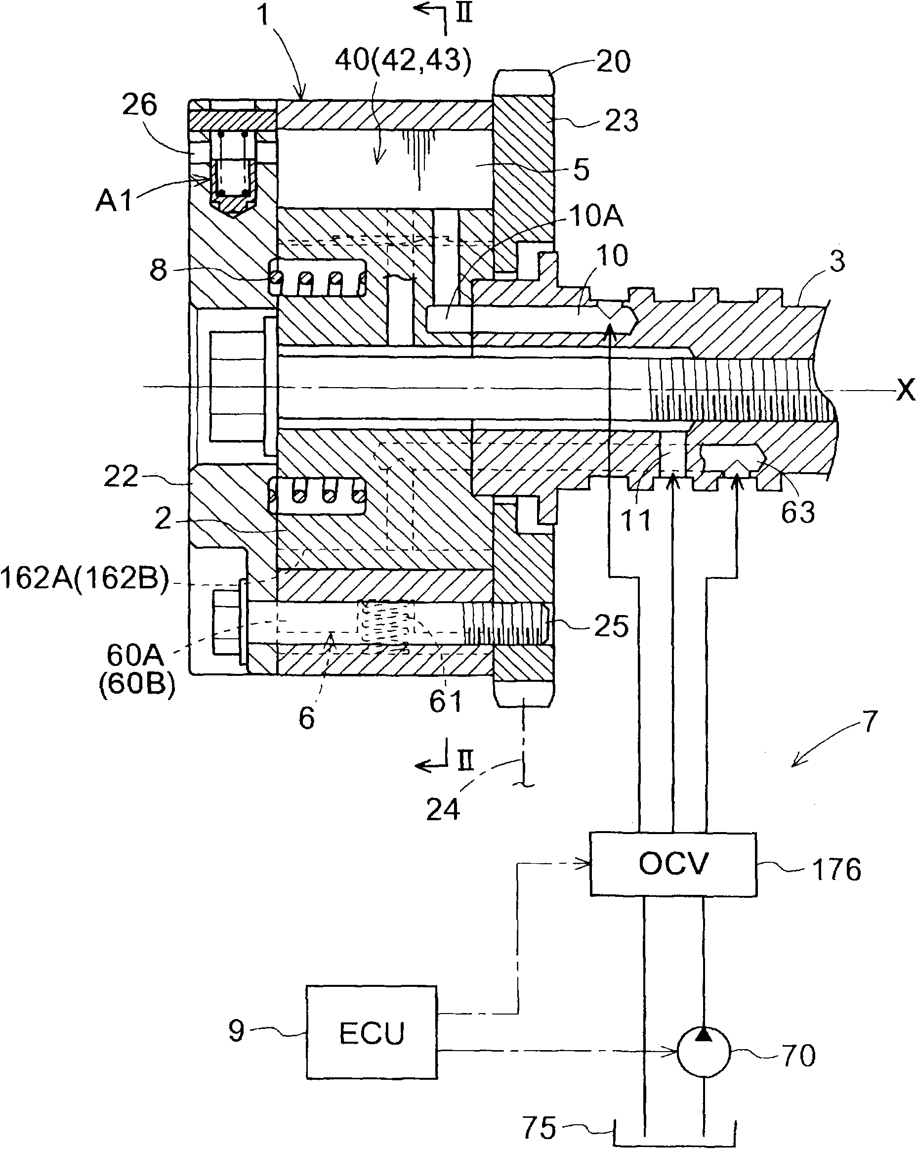
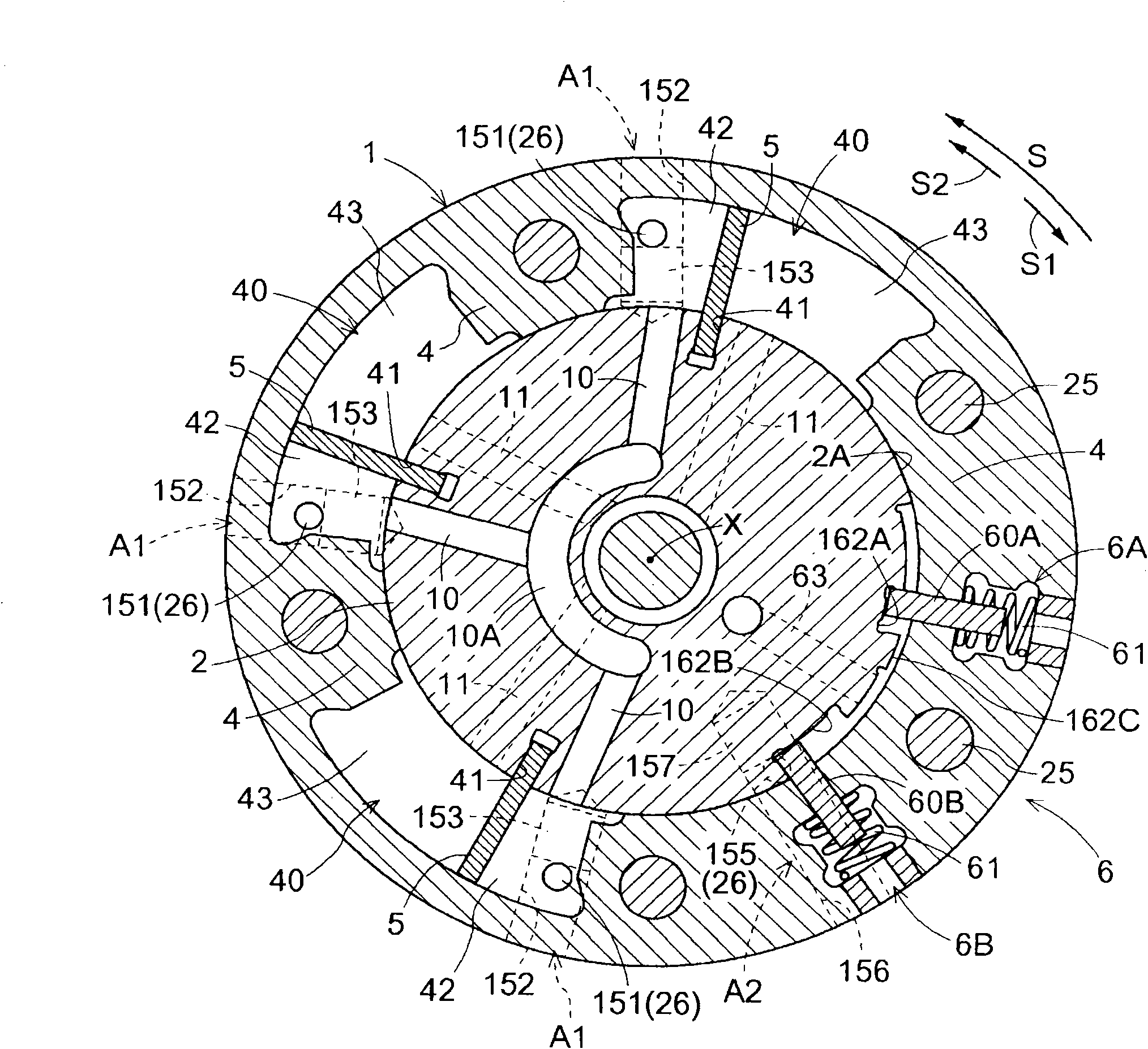
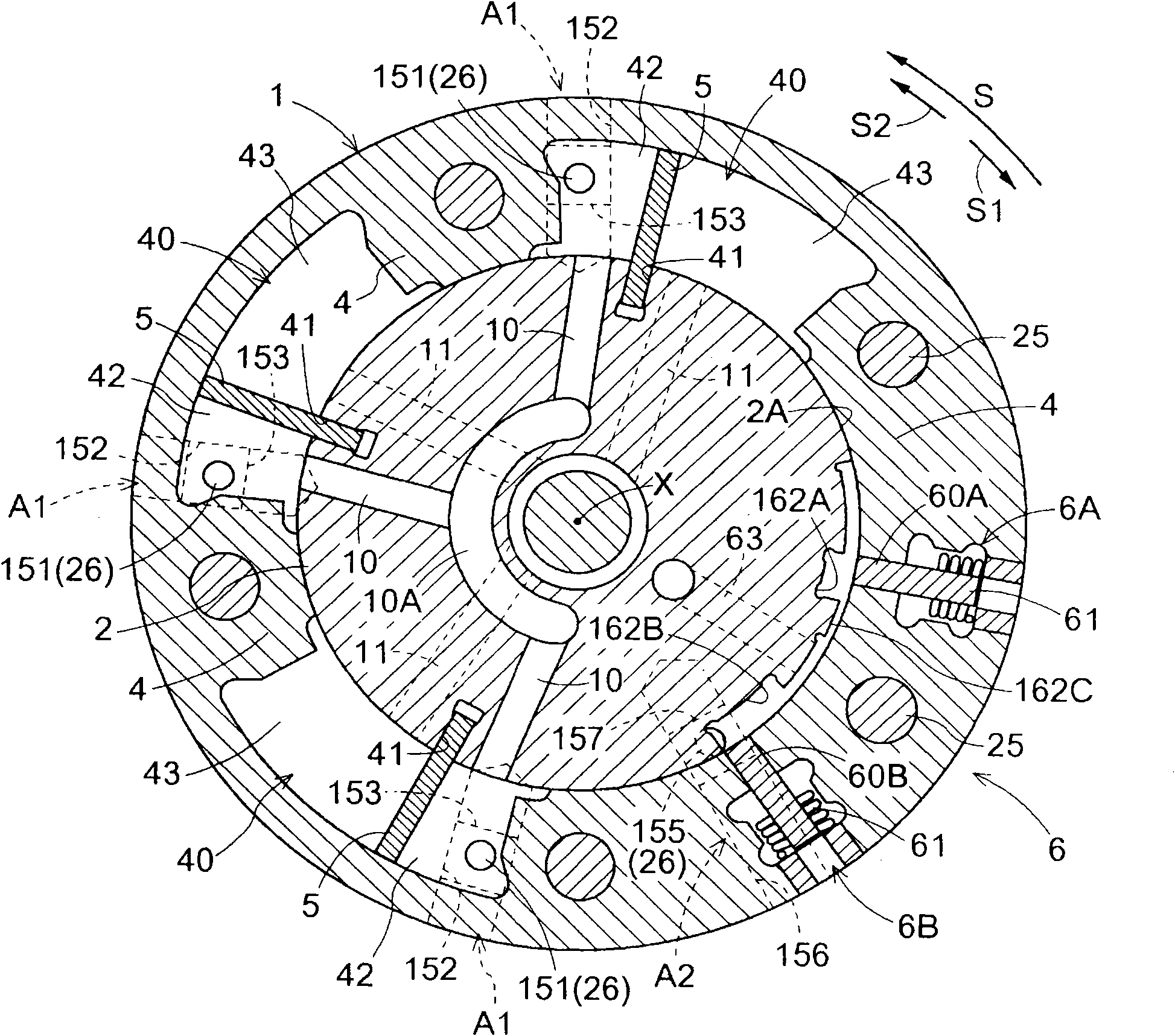
[0059] Below, according to the attached Figure 1 to Figure 9 , explains a first embodiment in which the valve timing control device is fitted at an intake valve of a vehicle engine. Figure 2 to Figure 5 A sectional view of the valve timing control device viewed from the rear plate 23 to the front plate 22 along the axial direction of the valve timing control device is shown.

[0060] [the whole frame]

[0061] Such as figure 1 and figure 2 As shown, the valve timing control apparatus according to the first embodiment includes an outer rotor 1 as a driving-side rotating member, and an inner rotor 2 as a driven-side rotating member. The outer rotor 1 rotates synchronously with the crankshaft of the engine (internal combustion engine). The inner rotor 2 is arranged coaxially with the camshaft 3 so that it can rotate synchronously with the camshaft 3 . The camshaft 3 controls the opening and closing operations of intake valves or exhaust valves provided at the combustion c...

no. 2 example

[0112] Refer to the accompanying drawings below Figure 10 to Figure 16 , to illustrate the second embodiment of the valve timing control device. The structural description of the valve timing control device similar to the first embodiment is omitted here, and more specifically, the description of the overall structure of the valve timing control device, the hydraulic chamber, and the torsion spring are omitted. Therefore, only the differences between the first embodiment and the second embodiment will be described below. In addition, the components in the second embodiment that are substantially the same as those in the first embodiment are assigned the same reference numerals and symbols as in the first embodiment. Figure 10 is a sectional view illustrating the overall structure of the valve timing control device according to the second embodiment as viewed in a direction orthogonal to the relative rotational axis X. FIG. Figure 11 It is a diagram illustrating a combinat...


PUM


Abstract

A valve timing control apparatus includes a driving-side rotating member (1), a driven-side rotating member (2) arranged coaxially with the driving-side rotational member so as to be rotatable relative to the driving-side rotating member (1), a retarded angle chamber (42) and an advanced angle chamber (43), each of which is defined by the driving-side rotating member (1) and the driven-side rotating member (2), a lock mechanism (6) locking a relative rotational phase of the driven-side rotating member (2) at a predetermined phase between a most advanced angle phase and a retarded angle phase,an operation fluid supply-and-discharge mechanism (76, 77, 176) supplying/discharging an operation fluid to/from the retarded angle chamber (42), the advanced angle chamber (43) and the lock mechanism (6), and a first air inlet mechanism (A1) for connecting one of the retarded angle chamber (42) and the advanced angle chamber (43) to an outside of the valve timing control apparatus in order to allow air to flow thereinto.

Description

technical field [0001] The invention relates to a valve timing control device, which is used to control the opening and closing timing of the intake valve and the exhaust valve of the vehicle internal combustion engine. Background technique [0002] Generally, according to an engine (internal combustion engine) having a locking mechanism used for a vehicle or the like, the phase formed between the driving side rotary member and the driven side rotary member is set at an appropriate initial phase so that the engine is started when the initial phase is formed. . Accordingly, the intake timing and ignition timing of the engine are optimized. [0003] JPH 11-173119A discloses a valve timing control device provided in an internal combustion engine having a locking mechanism. According to the valve timing control device disclosed in JPH 11-173119A, the phase formed between the driving side rotating member and the driven side rotating member when the internal combustion engine is...

Claims


Application Information

Patent Timeline
Patent Type & Authority Applications(China)
IPC IPC(8): F01L1/34
CPCF01L2800/03F01L2001/34483F01L2001/34473F01L2001/34463F01L1/3442F01L2001/34476F01L2001/34466
Inventor 铃木重光稻摩直人小林昌树池田宪治朝日丈雄宫地永治加藤优一三浦康孝
Owner AISIN SEIKI KK
Why Eureka
Try Eureka