Magnetic pump

A magnetic pump and pump body technology, applied in the direction of pumps, pump devices, pump components, etc., can solve the problems of reducing the ability of magnetic pump to transmit torque, speed ratio, and high cost, so as to improve the ability to transmit torque, realize The effect of rotating speed ratio and improving service life

Inactive Publication Date: 2010-09-01
SIEMENS CHINA
View PDF3 Cites 9 Cited by
  • Summary
  • Abstract
  • Description
  • Claims
  • Application Information

AI Technical Summary

Problems solved by technology

The drive rotor and the driven rotor of the sleeve type magnetic pump are installed concentrically, and it is easy to get stuck with the isolation sleeve due to deviation from the design point, so its installation and maintenance are relatively complicated. In order to avoid the above problems, it is generally necessary to increase the size of the drive rotor and The gap between the rotor and the spacer, thus reducing the magnetic field strength between the driving rotor and the driven rotor
Although the disc type magnetic drive pump does not have the problem that the driving rotor and the driven rotor are stuck with the spacer, since the magnetic pole area corresponding to the driving rotor and the driven rotor is smaller than that of the sleeve type, the distance between the driving rotor and the driven rotor The magnetic field strength is also relatively weak
These will reduce the ability of the magnetic pump to transmit torque
[0006] In addition, none of the above-mentioned existing pumps can realize the speed conversion ratio, and all of them need a motor with a specific speed to match it, while the speed of a general pump is much lower than that of a general-purpose motor, and the cost of a low-speed motor is much higher than that of a high-speed motor. If a high-speed motor is used, a reduction gearbox must be used, but the gearbox is easy to wear during use

Method used


Image

  • Magnetic pump
  • Magnetic pump
  • Magnetic pump

Examples


Embodiment Construction

[0039] In order to have a clearer understanding of the technical features, purposes and effects of the present invention, the specific implementation manners of the present invention will now be described with reference to the accompanying drawings. Wherein, the same parts adopt the same reference numerals.

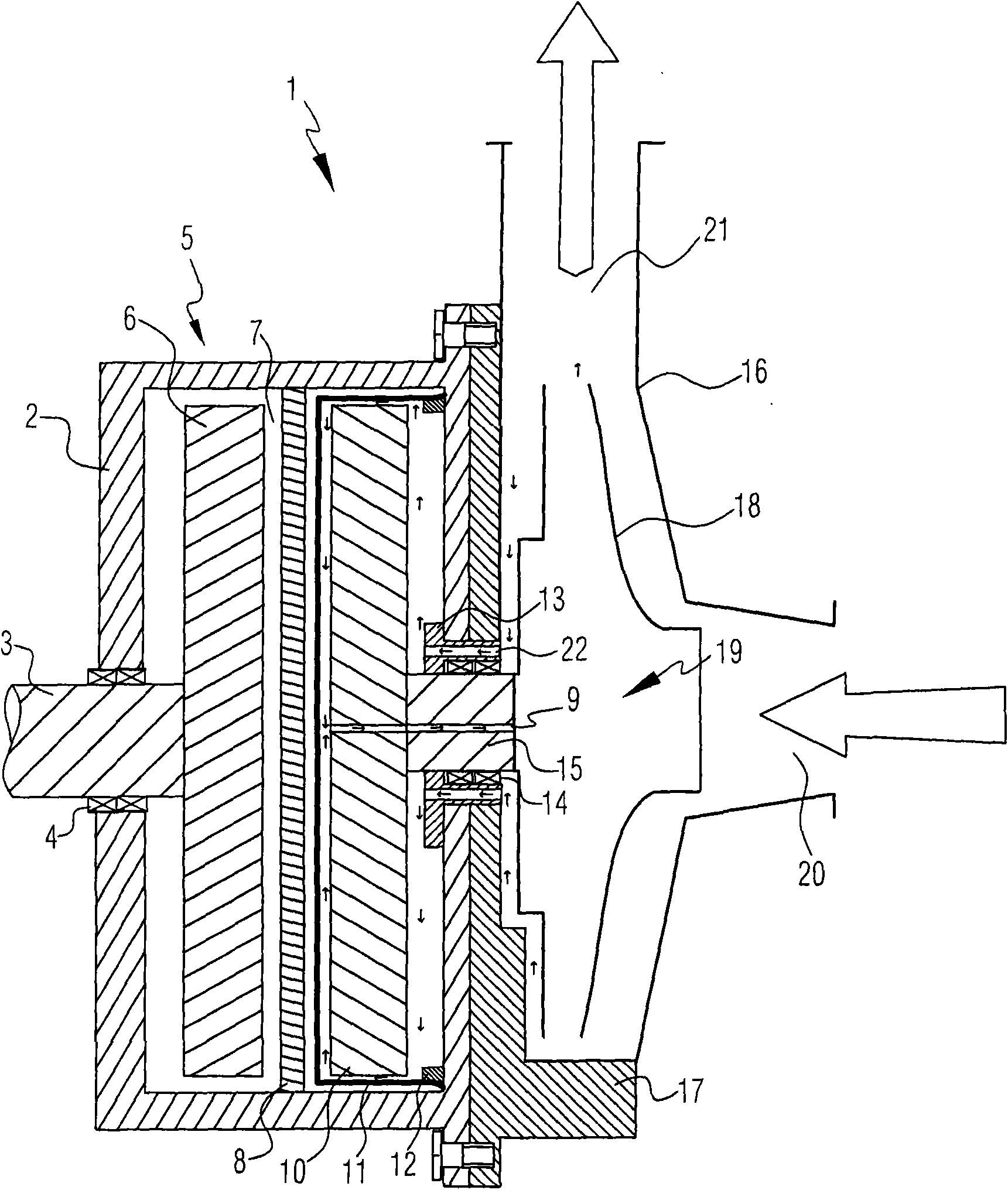
[0040] figure 1Shown is a schematic sectional view of a magnetic pump 1 according to the invention, wherein the magnetic pump 1 has a contactless magnetic gear 5 and a pump body 16 . The magnetic gears (magnetic gears) 5 shown in the figure are of disc type, of course, those skilled in the art should understand that this embodiment is only for illustration, and the magnetic gears 5 may also be of sleeve type.

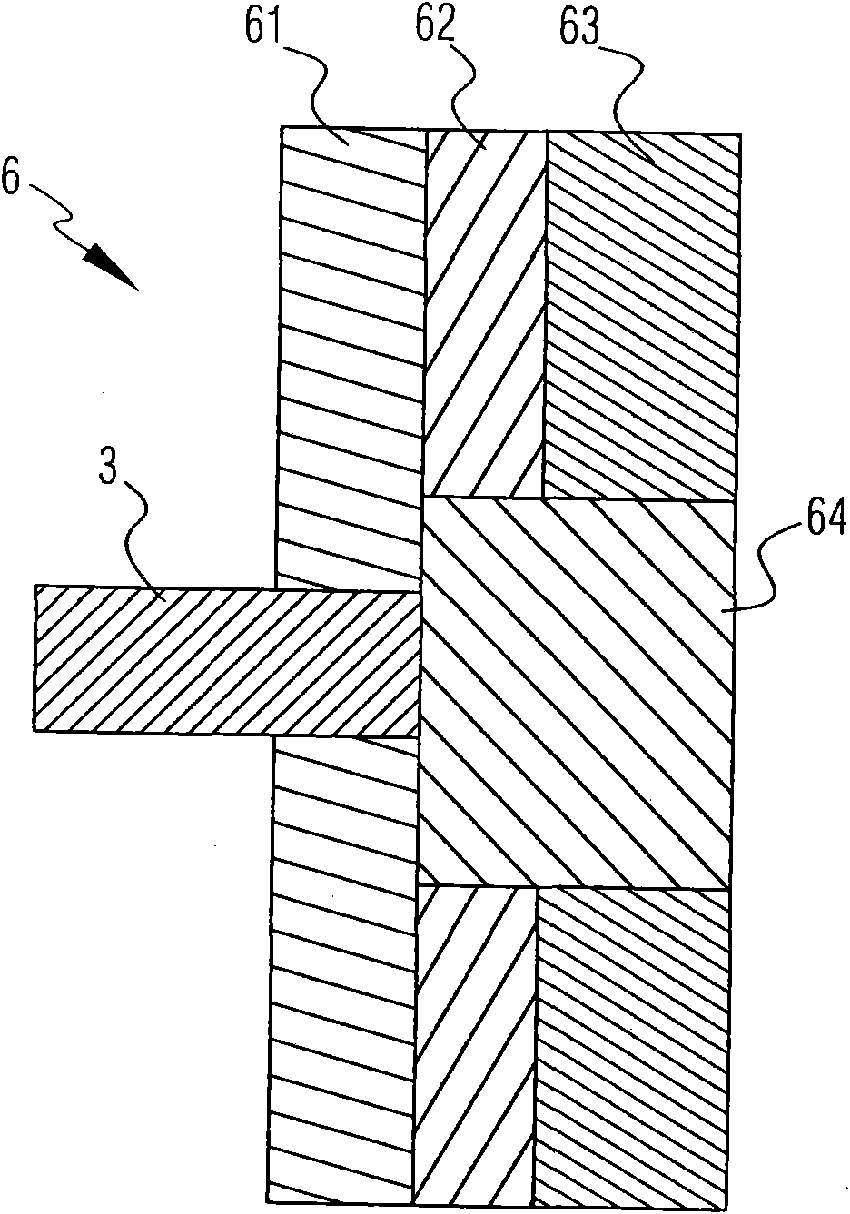
[0041] The magnetic gear 5 is an independent standard structural part, which includes a housing 2, in which a driving rotor 6, a driven rotor 10, a magnetic modulating part 8, a non-conducting Magnetic isolation sleeve 11 and a bearing seat 13. The driving rotor...


PUM


Abstract

The invention provides a magnetic pump, which comprises a magnetic gear (5) and a pump body (16). A driving rotor (6), a driven rotor (10) and a non-magnetic isolating sleeve (11) are arranged in the magnetic gear (5); and in another form, the driven rotor (10) can also be combined with the pump body (16) into a whole body. A magnetic field modulation component (8) is also arranged in the magnetic gear (5) and arranged between the driving rotor (6) and the driven rotor (10). Owing to the arrangement of the magnetic field modulation component (8), the magnetic field coupling between the driving rotor (6) and the driven rotor (10) is enhanced, the functions of torque transfer and rotation speed transformation ratio are realized, and the capacity of transferring torque of the magnetic pump is improved.

Description

technical field [0001] The invention relates to a magnetic force pump, in particular to a magnetic force pump with non-contact magnetic gear and compact structure. Background technique [0002] When transporting flammable, explosive, volatile, toxic, corrosive and precious liquids in chemical, petrochemical, pharmaceutical and other industries, it is required that the pump can only leak slightly or even not leak. Traditional mechanical pumps need to be equipped with complex dynamic seals, and it is difficult to ensure that they are absolutely leak-free during operation. Non-contact pumps are also known as sealless pumps or non-leakage pumps, which can be divided into magnetic pumps and canned pumps. They only have static seals but no dynamic seals in structure, so they can guarantee no leakage when transporting liquids. [0003] Magnetic pumps are also called magnetic drive pumps. Existing magnetic pumps, such as those disclosed in US 5269664A, US 5043592A, and US 4589822A,...

Claims


Application Information

Patent Timeline
Patent Type & Authority Applications(China)
IPC IPC(8): F04D13/06F04D29/18F04D29/00
Inventor 于尔李磊
Owner SIEMENS CHINA
Why Eureka
Try Eureka