LED lamp

A technology of LED lamps and LED chips, applied in the field of light sources, can solve problems such as shortened lifespan and unstable LED operation, and achieve the effects of increasing working lifespan, improving heat dissipation performance, and stabilizing work.

Inactive Publication Date: 2010-09-01
GUANGDONG HULUBAO CULTURE TECH CO LTD
View PDF4 Cites 29 Cited by
  • Summary
  • Abstract
  • Description
  • Claims
  • Application Information

AI Technical Summary

Problems solved by technology

[0003] However, the heat dissipation performance of the LED lamp is extremely critical. Excessively high temperature will cause the LED to wo

Method used


Image

  • LED lamp
  • LED lamp
  • LED lamp

Examples


Example Embodiment

[0028] In order to describe the technical content, structural features, achieved goals and effects of the present invention in detail, the following will be described in detail in conjunction with the embodiments and accompanying drawings.

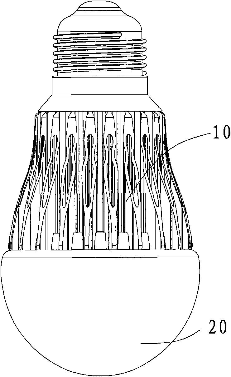
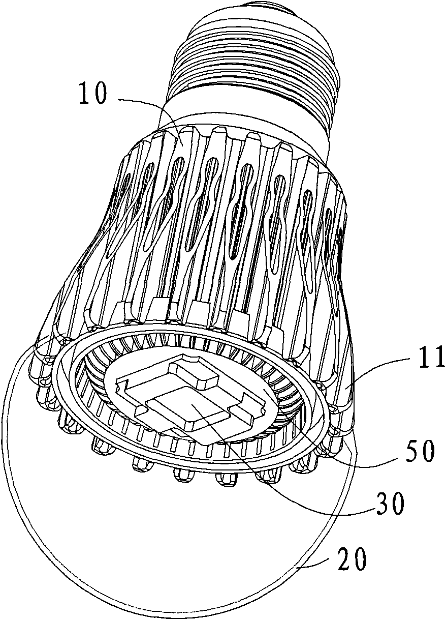
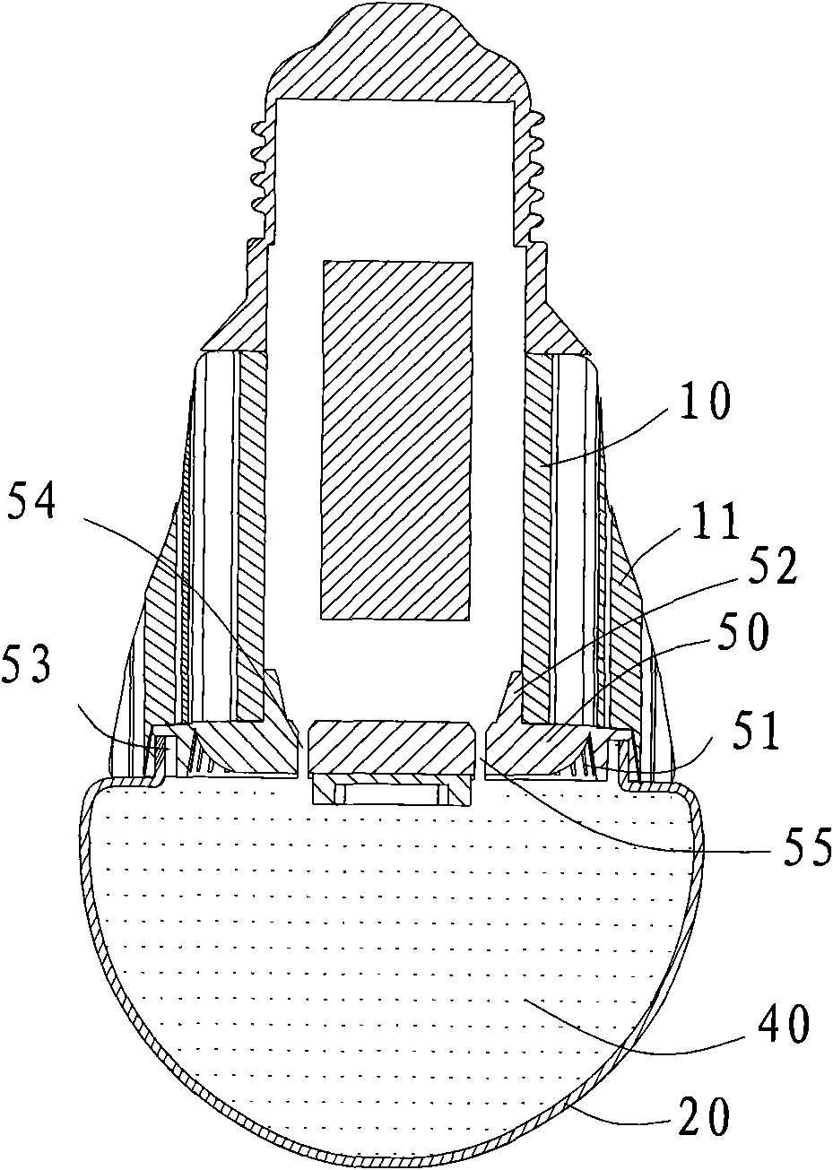
[0029] see figure 1 , figure 2 as well as image 3 The embodiment of the LED lamp of the present invention includes a heat dissipation base 10, a lampshade 20 and an LED chip 30, the lampshade 20 is fixed on the heat dissipation base 10, the LED chip 30 is located in the lampshade 20, and the lampshade 20 is filled with There is heat transfer gas 40 .

[0030] When working, the heat emitted by the LED chip 30 can be dissipated through the heat dissipation base 10 on the one hand, and on the other hand, heat the heat-conducting gas 40 in the lampshade 20 to make it flow, and the hot gas reaches the inner wall of the lampshade 20, and the heat is transferred to the lampshade 20. The lampshade 20 conducts and radiates heat to the outside ...


PUM


Abstract

The invention discloses an LED lamp which comprises an LED chip, a heat dissipation base and a lampshade, wherein the lampshade is fixed on the heat dissipation base, the LED chip is positioned in the lampshade, and the lampshade is filled with the heat conduction gas. The LED lamp promotes the heat dissipation property by a large extent and can work better at lower temperature.

Description

technical field [0001] The invention relates to a light source, in particular to an LED lamp. Background technique [0002] The prior art LED bulb generally includes a radiator, a spherical lampshade, and an LED chip. One end of the radiator is a lamp cap, and the other end of the radiator is fixed to the LED chip and the lampshade. [0003] However, the heat dissipation performance of the LED lamp is extremely critical. Too high temperature will cause the LED to work unstable and even shorten the life. The LED chip in the prior art LED lamp can only dissipate heat through the heat dissipation base on it. [0004] Therefore, it is necessary to design LED lamps with better heat dissipation effect and simple structure to meet the needs of the LED lamp market. Contents of the invention [0005] The technical problem mainly solved by the present invention is to provide an LED lamp whose heat dissipation performance is greatly improved and can work better at a lower temperatur...

Claims


Application Information

Patent Timeline
IPC IPC(8): F21S2/00F21V17/00F21V19/00F21V29/00F21Y101/02F21V29/503F21V29/74
Inventor 蔡鸿
Owner GUANGDONG HULUBAO CULTURE TECH CO LTD
Why Eureka
Try Eureka