Coated article with niobium chromium inclusive barrier layer(s) and method of making same

a technology of niobium chromium and barrier layer, which is applied in the direction of natural mineral layered products, layered products, chemistry apparatus and processes, etc., can solve the problems of nicr (or nicrn/sub>x/sub>) layers lacking in chemical durability, nicr is susceptible to significant damage, and nicr is easy to be damaged. , to achieve the effect of improving chemical durability, excellent thermal performance and excellent chemical durability

Active Publication Date: 2005-12-13
GUARDIAN GLASS LLC
View PDF17 Cites 57 Cited by
  • Summary
  • Abstract
  • Description
  • Claims
  • Application Information

AI Technical Summary

Benefits of technology

[0008]Surprisingly, it has been found that the addition of Cr to Nb causes the resulting layer (and thus the resulting coated article) to realize excellent chemical durability, and also excellent thermal performance. For example, the use of NbCrNx may allow the resulting coated article(s) to achieve at least one of: (a) improved chemical durability such as corrosion resistance to alkaline solutions (e.g., NaOH) and / or acid (e.g., HCl); (b) good thermal performance; (c) good mechanical performance such as scratch resistance due at least in part to the material's good affinity to both IR reflecting materials such as silver and dielectrics such as silicon nitride; and / or (d) low ΔE* values upon heat treatment.

Problems solved by technology

While such coatings are certainly good overall coatings usable in applications such as windshields and architectural windows, they tend to be problematic in certain respects.
For example, while such layer stacks with NiCr contact layers (a “contact layer” is a layer which contacts an IR reflecting layer such as silver) provide efficient solar control and are overall good coatings, the NiCr (or NiCrNx) layers are lacking in terms of chemical durability.
For instance, NiCr is susceptible to significant damage when exposed to acid such as HCl.
Unfortunately, Nb layers are also lacking with respect to chemical durability.
In particular, Nb suffers damage when exposed to certain chemicals such as alkaline solutions, e.g., upon exposure to a one hour NaOH boil test for measuring durability.
In commercial use, pinholes can form in dielectric layer(s) thereby exposing the contact layer(s) in certain areas; and if it is damaged by alkaline solutions this can lead to durability issues and coating failure.
Unfortunately, this oxidation of the NbCr alloy layer can cause the ΔE* value of the coated article to be unduly high if and when heat treatment occurs.

Method used


Image

  • Coated article with niobium chromium inclusive barrier layer(s) and method of making same
  • Coated article with niobium chromium inclusive barrier layer(s) and method of making same
  • Coated article with niobium chromium inclusive barrier layer(s) and method of making same

Examples


example 1

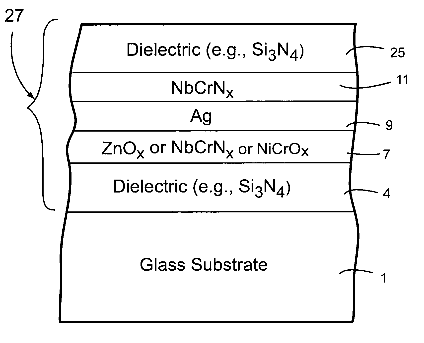
[0039]In Example 1, a nitrided NbCr layer (i.e., NbCrNx) was deposited via sputtering using a power of 1.0 kW, a voltage of 465 V, a line speed of 33 inches per minute (two passes), argon (Ar) gas flow of 30 sccm, and nitrogen (N) gas flow of 15 sccm (using an ILS lab coater). After two passes, this resulted in a NbCrNx layer about 230 Å thick. This may be too thick for a contact layer, but may well be used for an IR reflecting layer in a solar control coating. This example is merely for providing an example of how to deposit and form a nitrided NbCr layer, and thinner layers may be deposited by merely increasing the line speed, reducing the number of passes, and / or the like. Further details concerning such nitrided NbCr inclusive layers according to such embodiments are described in U.S. Ser. No. 10 / 370,060, filed Feb. 21, 2003, the disclosure of which is hereby incorporated herein by reference.

example 2

[0040]In Example 2, a nitrided NbCr layer (i.e., NbCrNx) was deposited via sputtering using a power of 1.0 kW, a voltage of 444 V, a line speed of 30 inches per minute (two passes), argon (Ar) gas flow of 30 sccm, and nitrogen (N) gas flow of 12 sccm (using an ILLS lab coater). After two passes, this resulted in a NbCrNx layer about 240 Å thick. Again, this may be too thick for a contact layer, but may well be used for an IR reflecting layer in a solar control coating. This example is merely for providing another example of how to deposit and form a nitrided NbCr layer, and thinner layers may be deposited by merely increasing the line speed, reducing the number of passes, and / or the like as will be appreciated by those skilled in the art.

example 3

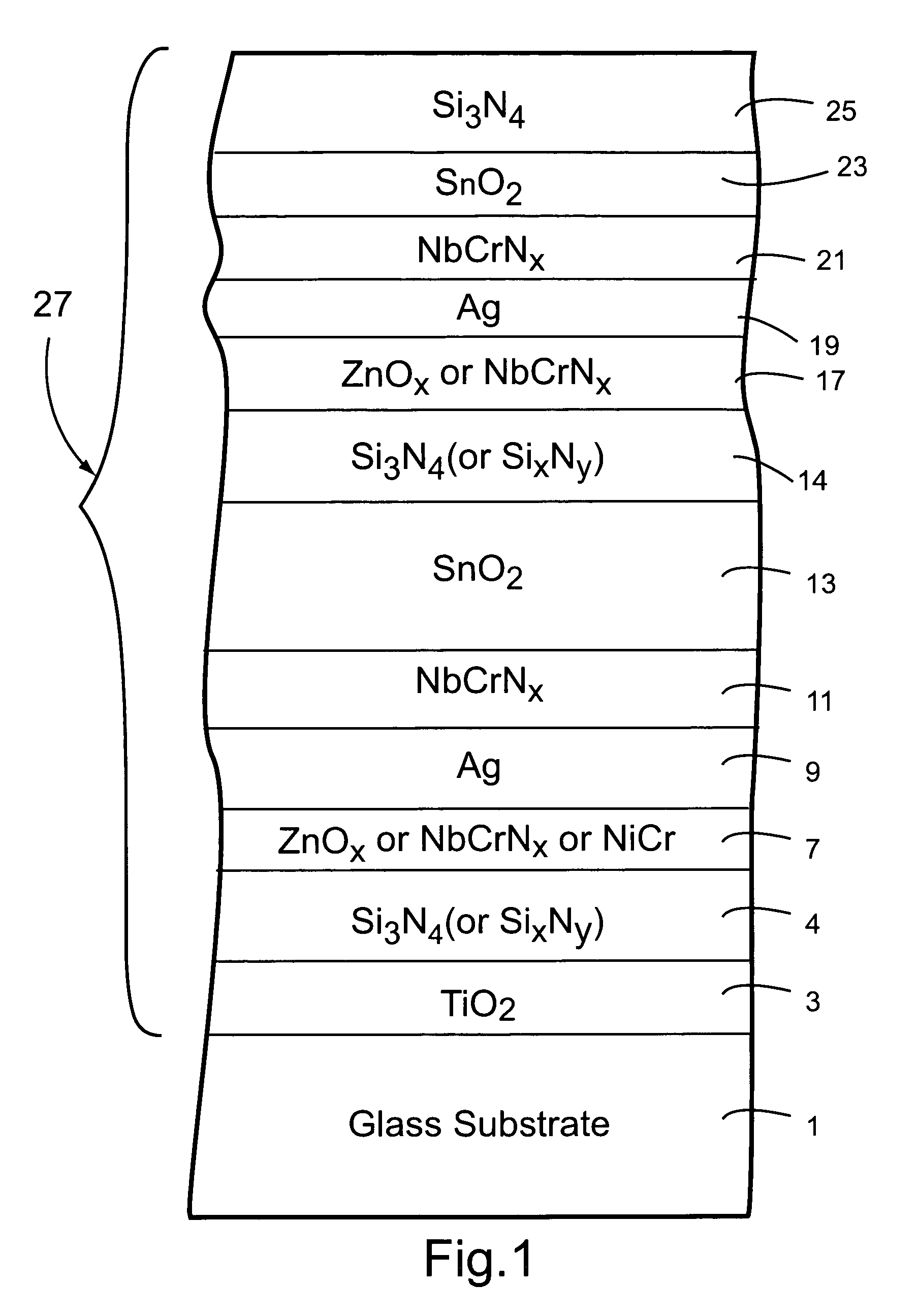
[0041]In hypothetical Example 3, a layer stack is set forth below with the layers in the stack being listed from the glass substrate outwardly:

[0042]

TABLE 5Layer Stack for Example 3LayerThicknessGlass Substrateabout 3 to 3.4 mmTiOx 40 ÅSixNy113 ÅZnAlOx100 ÅAg 95 ÅNbCrNx 15 ÅSnO2483 ÅSixNy113 ÅNbCrNx 15 ÅAg131 ÅNbCrNx 15ÅSnO2100 ÅSi3N4226 Å

[0043]An example process which may be used to form the coated article of Example 3 is set forth below. For this hypothetical process, the gas flows (argon (Ar), oxygen (O), and nitrogen (N)) in the below table are in units of ml / minute, and include both tuning gas and gas introduced through the main. The λ setting in the sputter coater is in units of mV, and as will be appreciated by those skilled in the art is indicative of the partial pressure of the gas being used in the sputter chamber (i.e., a lower λ setting indicates a higher oxygen gas partial pressure). Thus, for example, a lower λ setting in the case of depositing a ZnAlO layer would mean...


PUM

PropertyMeasurementUnit
sheet resistanceaaaaaaaaaa
thickaaaaaaaaaa
thickaaaaaaaaaa

Abstract

A coated article is provided so as to include a coating (e.g., low-E coating, or the like) having at least one layer of or including niobium chromium (NbCr). The NbCr layer may be nitrided. The NbCr inclusive layer (e.g., NbCrNx) may be provided as any suitable layer of the multi-layer coating, but in certain example instances may be used as a contact layer adjacent to an infrared (IR) reflecting layer. Coated articles herein may be used in the context of insulating glass (IG) window units, laminated windows, architectural or residential monolithic window units, vehicle window units, and/or the like.

Description

[0001]This application relates to a coated article for use in a window or the like, wherein the coated article includes a niobium chromium inclusive layer(s) (e.g., NbCrNx). In certain example instances, the niobium chromium inclusive layer(s) may be used as a barrier layer or contact layer located immediately adjacent and contacting an infrared (IR) reflecting layer such as a silver inclusive layer.BACKGROUND OF THE INVENTION[0002]Windows including glass substrates with solar control coatings provided thereon are known in the art. Such windows may be used in the context of architectural windows, insulating glass (IG) window units, automotive windows, and / or the like.[0003]U.S. Pat. No. 5,514,476 discloses a coated article having a layer stack of glass / SiN / NiCr / Ag / NiCr / SiN, where SiN stands for silicon nitride. While such coatings are certainly good overall coatings usable in applications such as windshields and architectural windows, they tend to be problematic in certain respects....

Claims


Application Information

Patent Timeline
Patent Type & Authority Patents(United States)
IPC IPC(8): B32B17/06B32B9/00B32B17/00C03CE06B3/24
CPCC03C17/36C03C17/3613C03C17/3626C03C17/3639C03C17/3644C03C17/366C03C17/3681
Inventor STACHOWIAK, GRZEGORZ
Owner GUARDIAN GLASS LLC
Why Eureka
Try Eureka