
Electrical connector

一种电连接器、插头连接器的技术,应用在连接、固定连接、连接装置的零部件等方向,能够解决牢固性的改进不能令人满意、不能流过等问题,达到小型化总体高度、窄导体间距、减小总体高度的效果

Inactive Publication Date: 2010-09-01
APPLE INC
View PDF7 Cites 27 Cited by
  • Summary
  • Abstract
  • Description
  • Claims
  • Application Information

AI Technical Summary

Problems solved by technology

[0008] For the configurations disclosed in the above-mentioned patent documents, although they meet the requirements for narrower conductor spacing and miniaturization and reduced overall height of the connector, their improvement of the firmness against accidental force during operation is not impressive. Satisfactory, and about 1A cannot flow without using multiple terminals as one current supply unit

Method used


Image

  • Electrical connector
  • Electrical connector
  • Electrical connector

Examples


Embodiment Construction

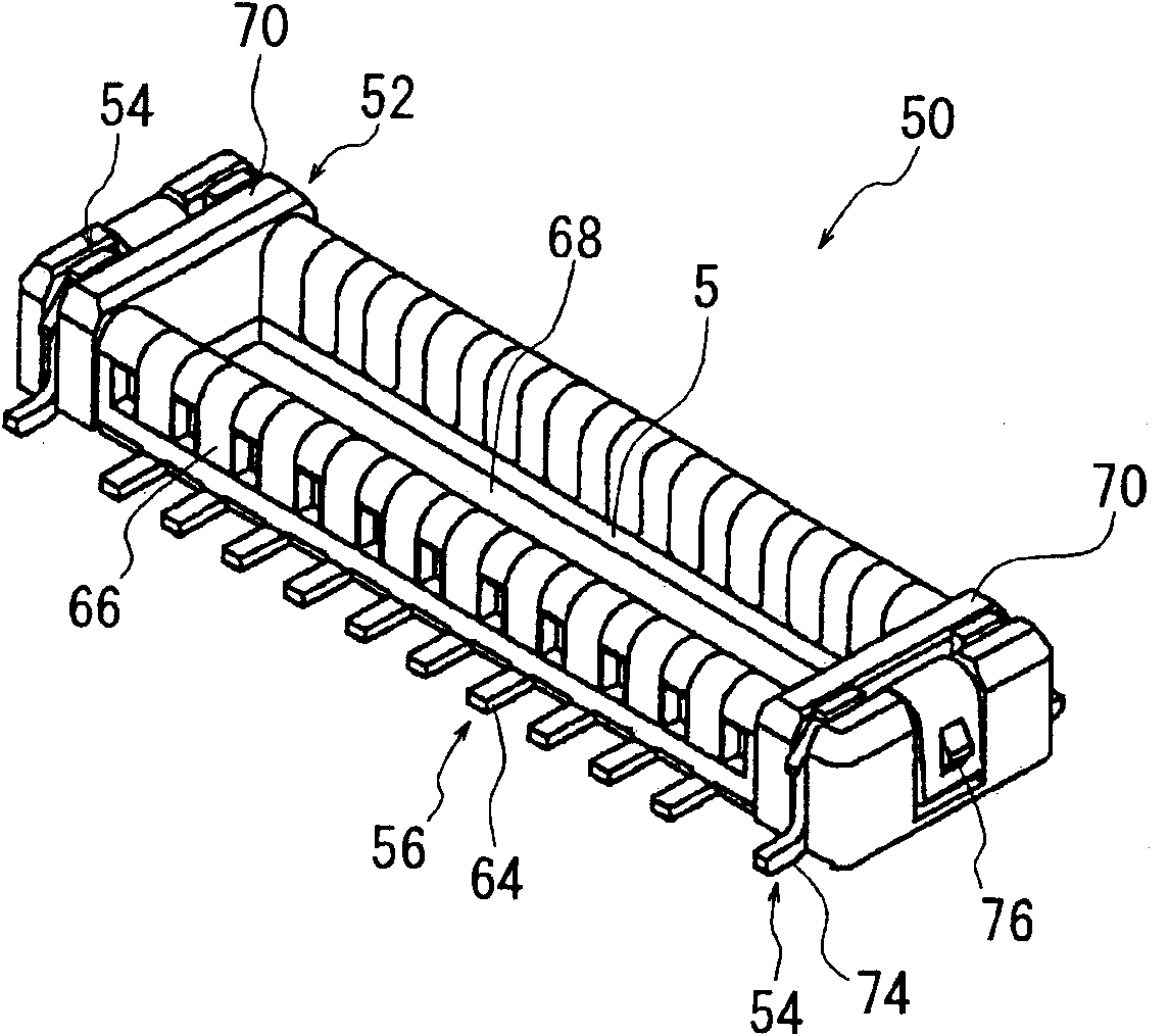
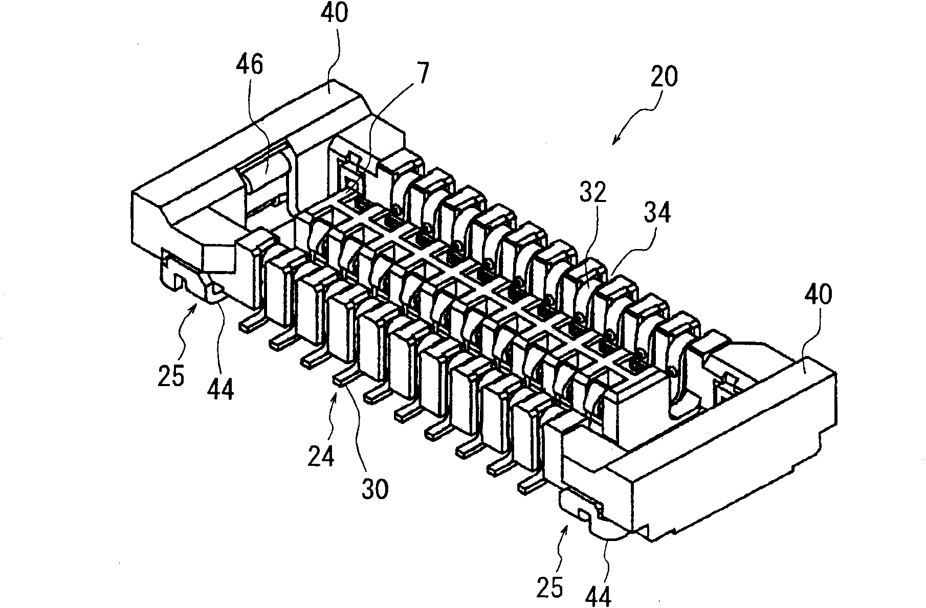
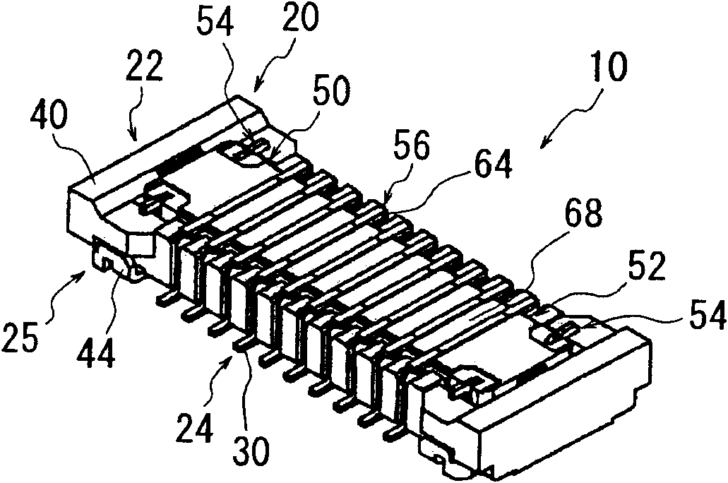
[0036] The subject matter of the present invention is characterized by an electrical connector 10 for connecting substrates, the electrical connector 10 comprising a receptacle connector 20 and a plug connector 50 assembled detachably from each other, the receptacle connector 20 comprising A plurality of socket contacts 24 and a block body 22 for arranging and holding the socket contacts 24, each of the socket contacts 24 has a first contact portion 26 adapted to contact with a mating contact, fixed to the block body 22 The first fixing portion 28 and the first connection portion 30 connected to one of the substrates, the plug connector 50 includes a plurality of plug contacts 56 and a housing 52 for arranging and holding the plug contacts 56 , the plug contacts 56 each have a second contact portion 58 adapted to contact the receptacle contact 24, a second fixing portion 60 fixed to the housing 52, and a second contact portion connected to another substrate. Two connecting par...


PUM


Abstract

An electrical connector includes a receptacle connector and a plug connector. A first fixture and a second fixture are each arranged on at least one end in the longitudinal direction of the receptacle and plug connectors, respectively. The first and second fixtures each have connection portions to be connected to a respective substrate. The first and second fixtures include at least three engaging portions and at least three anchoring portions, respectively. The engaging portions and anchoring portions are adapted to engage each other. At least one set of the engaging and anchoring portions engaged each other is caused to be in electrical continuity to use as a power supply connection. The electrical connector thus constructed is capable of sufficiently withstand any accidental external force when being fitted, and is also capable of ensuring a power supply connection without using many terminals, while keeping narrower pitches of conductors, and miniaturization and reduced overall height of the electrical connector.

Description

technical field [0001] The present invention relates to electrical connectors for use with electrical and electronic devices such as cellular phones, small personal computers, etc., and more particularly, the present invention relates to an electrical connector that can withstand accidental force The electrical connection is adequately maintained, and the retainer of such a connector serves as a power contact in addition to its inherent function. Background technique [0002] Generally, when interconnecting substrates, two connectors are generally used, both of which have their respective substrates connected thereto by soldering or the like, and which are connected to each other. [0003] Incorporated herein as examples of such a connector for connecting substrates proposed by the applicant of this patent application are Japanese Utility Model Publication No. H05-69,873 (1993) (Patent Document No. 1), Japanese Utility Model Publication No. Japanese Utility Model Publicatio...

Claims


Application Information

Patent Timeline
Patent Type & Authority Applications(China)
IPC IPC(8): H01R12/16H01R13/639H01R12/00H01R12/71H01R12/78H01R12/79H01R12/91
CPCH01R12/716H01R13/20H01R12/57H01R12/73
Inventor 佐藤一宏加藤宽道高桥宏和
Owner APPLE INC
Learn More