Charging dock for chargeable hand-held device

A technology for handheld devices and charging stands, which is applied to battery circuit devices, circuits, current collectors, etc. It can solve the problems of unsightly appearance of the charging jack, affecting the charging capacity of the battery, and the jack is easy to be polluted and blocked, so as to improve the charging efficiency. , The connection is durable and easy to pull out

Active Publication Date: 2010-09-01
LED LENSER CORP
View PDF1 Cites 40 Cited by
  • Summary
  • Abstract
  • Description
  • Claims
  • Application Information

AI Technical Summary

Problems solved by technology

[0004] These handheld devices usually have a charging jack. The disadvantage of this structure is that the jack is easy to be polluted and blocked after a long time, thus affecting the long-term charging ability of the battery.
In addition, the charging jack is not aesthetically pleasing in appearance
[0005] In addition, another disadvantage of the existing charging devices, especially the charging devices for handheld devices, is that after the charging is completed, the device to be charged must be able to be pulled out from the charging stand as quickly as possible.
For example, flashlights or similar equipment in other police and firefighting equipment must be unplugged from the charger after the alarm bell is sounded, and in this case, the plug-in device currently used is easily damaged

Method used


Image

  • Charging dock for chargeable hand-held device
  • Charging dock for chargeable hand-held device
  • Charging dock for chargeable hand-held device

Examples


Embodiment Construction

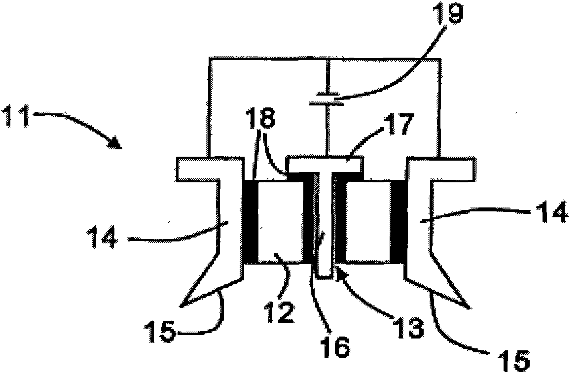
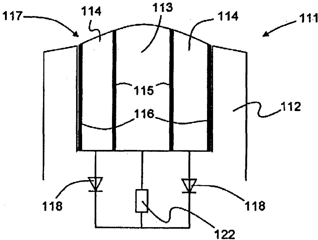
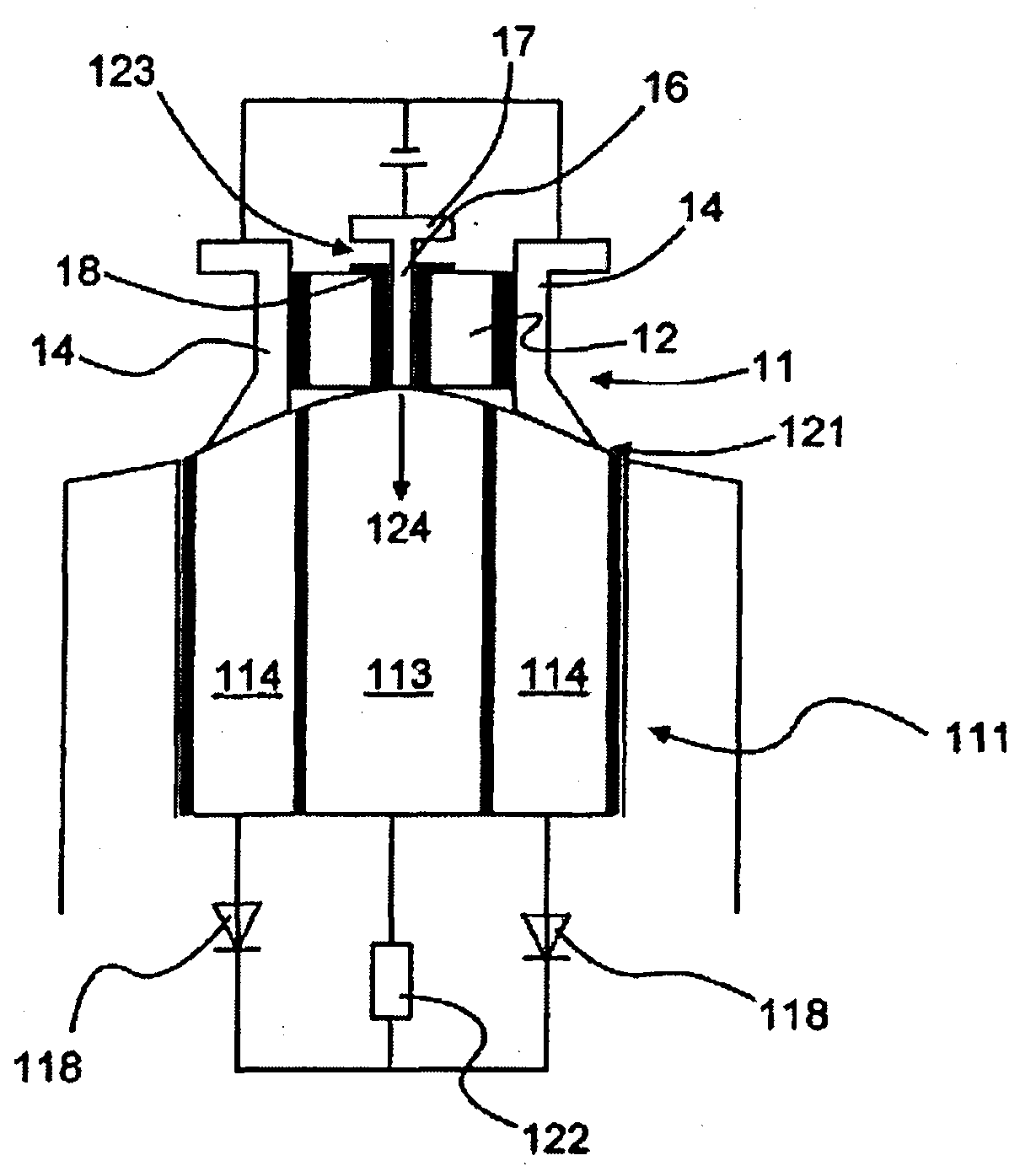
[0033] The main improved part of the charging stand provided by the present invention is the contact device. Therefore, only the charging contact arrangement will be described in detail below. as attached Figure 1~3 As shown, the charging contact device 11 has a ring-shaped magnet 12 with a hole 13 in the center, and the outer periphery of the magnet 12 is provided with a charging contact ring 14 with a slope 15 on the bottom surface, and the one passing through the middle hole 13 of the magnet is made of paramagnetic material The charging contact pin 16 has a ferromagnetic disk 17 at the top of the charging contact pin 16, and its radius is larger than the radius of the central hole 13 of the magnet 12, so that it can be effectively connected with the magnet 12. Between the charging contact ring 14 , the charging contact pin 16 and the magnet 12 there is an insulating assembly 18 . Of course, the charging contact ring 14 and the charging contact pin 16 will be connected wi...


PUM


Abstract

The invention discloses a charging dock for a chargeable hand-held device, which overcomes the disadvantages of the conventional charger, in particular that meets the requirement of beautiful charger contact and allows the hand-held device to be quickly decoupled from the charging dock. The charging dock has a charger contact device (11) including annular magnets (12), which are brought in operative contact with ferromagnetic material. Another charger contact device (111) is provided in a hand-held device (112) that is partially formed from ferromagnetic material. The contact device (11) of the charging dock and the contact device (111) of the hand-held device (112) are correspondingly brought in contact in a common charging system (121).

Description

technical field [0001] The invention relates to a charging stand (or charging device) suitable for a rechargeable handheld device, especially suitable for a pocket flashlight equipped with a contact device for charging. Background technique [0002] Most existing charging cradles use a plug to plug into a handheld device for charging, or vice versa. In other words, a common charging device should usually at least consist of a plug and a matching socket. Currently, this is the case with charging devices for mobile phones, laptop computers or digital cameras. [0003] Existing patents have been related to this type of charging stand. For example, DE 29721015U1 has disclosed an invention patent for a charging stand for rechargeable handheld devices. This type of charging stand includes a bracket for the handheld device and a power plug. The handheld device to be charged can be inserted into the surface or inside of the bracket; the power plug can charge the handheld device fi...

Claims


Application Information

Patent Timeline
Patent Type & Authority Applications(China)
IPC IPC(8): H01R31/00H01R13/62H01R13/22H01R13/66H02J7/00
CPCH01R13/22H01R13/6205H02J7/0042
Inventor 雷德·斯德生
Owner LED LENSER CORP
Why Eureka
Try Eureka