Heat exchange and flow guide structure of hot water storage tank

A technology for heat storage tanks and heat exchange tanks, which is applied to heat storage equipment, heat exchange equipment, heat exchanger types, etc., and can solve problems such as reduced water volume, mixed water in the heat storage tank, and failure to meet the required operating temperature

Inactive Publication Date: 2010-09-08
李博峰
View PDF2 Cites 5 Cited by
  • Summary
  • Abstract
  • Description
  • Claims
  • Application Information

AI Technical Summary

Problems solved by technology

[0002] At present, in industrial and civil hot water supply systems, the method of placing a heat exchanger in a volumetric hot water storage tank to obtain hot water is due to the improper structure of the heat exchanger, which leads to the phenomenon of water mixing in the hot water storage ta

Method used


Image

  • Heat exchange and flow guide structure of hot water storage tank
  • Heat exchange and flow guide structure of hot water storage tank
  • Heat exchange and flow guide structure of hot water storage tank

Examples


Embodiment 1

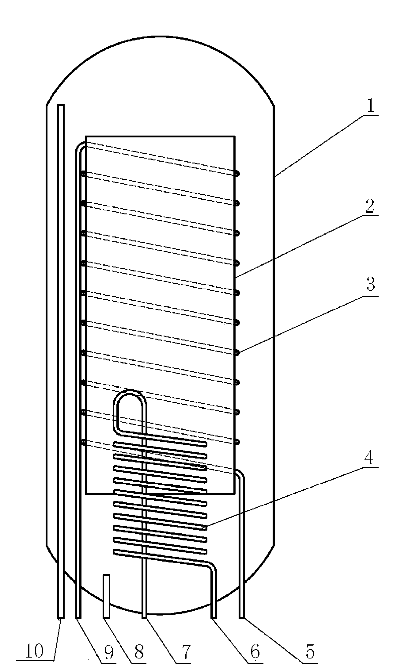
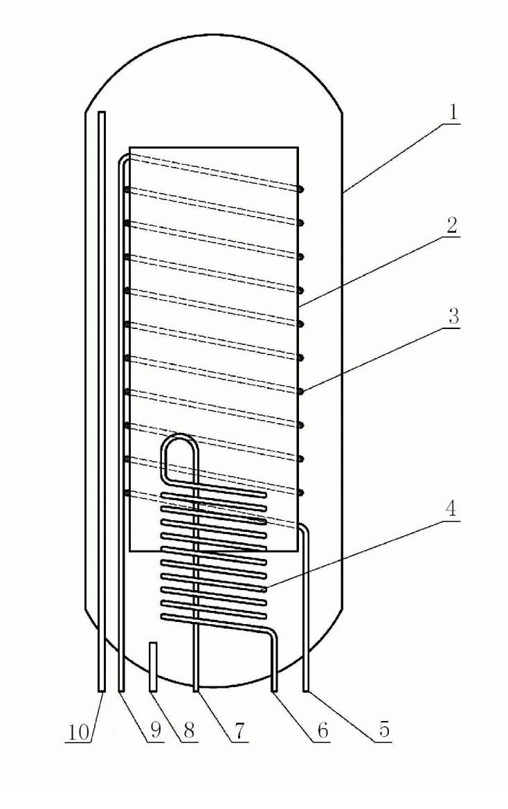
[0013] Embodiment 1 of the present invention will refer to the appended figure 1 To describe, 8 tank inlets and 5 heat inlets are connected to tap water pipelines, 6 heat source outlets and 7 heat source inlets are respectively connected to the cold end and hot end of the heat source, and 9 heat extraction outlets are connected to the hot water end.

[0014] Fill tank 1 with water through the inlet of tank 8 until the outlet of tank 10 leaves water. The heat source medium enters the 4 heat source heat exchanger through the 7 heat source inlet to exchange heat with the water in the tank, and flows out through the 6 heat source outlet, and the temperature of the heat storage medium water in the tank increases. The cold water enters the 3 heat exchanger through the 5 heat extraction inlet and exchanges heat with the heat storage medium and flows out through the 9 heat extraction outlet to be used. The heat storage medium in the guide tube moves upward, and the heat storage mediu...

Embodiment 2

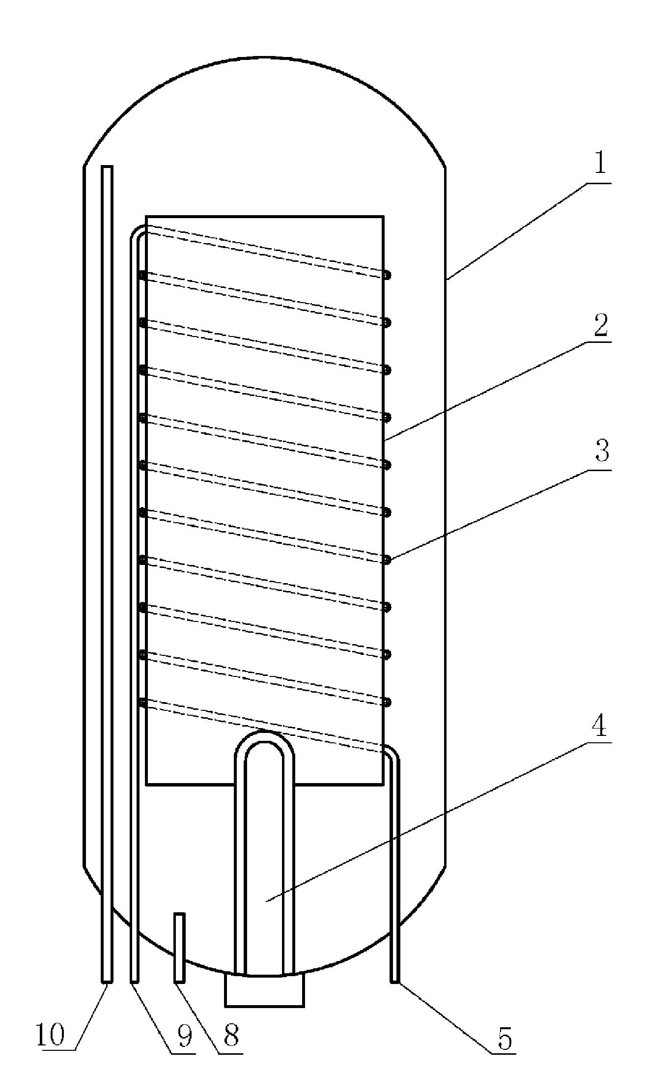
[0016] An embodiment of the present invention that uses different heating methods for the heat source heat exchanger described in the heat exchange and flow guide structure of the hot water storage tank. This example adopts the electric heating method.

[0017] Embodiment 2 of the present invention will refer to the appended figure 2 For description, 8 tank inlets and 5 heat inlets are connected to the tap water pipeline, and 9 heat outlets are connected to the hot water end.

[0018] Fill tank 1 with water through the inlet of tank 8 until the outlet of tank 10 leaves water. Turn on the power switch of the electric heater, and the temperature of the heat storage medium water in the tank increases. The cold water enters the 3 heat exchanger through the 5 heat extraction inlet and exchanges heat with the heat storage medium and flows out through the 9 heat extraction outlet to be used. The heat storage medium in the guide tube moves upward, and the heat storage medium in the...


PUM


Abstract

The invention relates to a heat exchange and flow guide structure of a hot water storage tank, which realizes temperature layering of thermal mediums in a hot water storage tank in the using process and avoids mixing of cold water and hot water in the hot water storage tank, so that the water outlet temperature of a heat exchanger is stably maintained above the required temperature for a long time, the produced water which can meet using requirement is increased and the heat utilization efficiency in the hot water storage tank is sufficiently improved.

Description

technical field [0001] The invention relates to a structure of heat exchange equipment, in particular to a structure of heat exchange equipment for obtaining hot water from a volumetric hot water storage tank in a flow-through manner and avoiding mixing of cold and hot water in the hot water storage tank. Background technique [0002] At present, in industrial and civil hot water supply systems, the method of placing a heat exchanger in a volumetric hot water storage tank to obtain hot water is due to the improper structure of the heat exchanger, which leads to the phenomenon of water mixing in the hot water storage tank, which makes the The temperature in the hot water storage tank drops rapidly and causes the outlet water temperature of the heat exchanger to drop accordingly, failing to reach the required use temperature, and the amount of water that can meet the use is reduced, resulting in energy waste. Contents of the invention [0003] The invention provides a heat e...

Claims


Application Information

Patent Timeline
IPC IPC(8): F28D20/00F28F9/00
CPCY02E60/142Y02E60/14
Inventor 李博峰
Owner 李博峰
Why Eureka
Try Eureka