Eureka AIR delivers breakthrough ideas for toughest innovation challenges, trusted by R&D personnel around the world.

High-temperature and high-pressure small-size length measuring device

A length measuring device, high temperature and high pressure technology, applied in the direction of measuring devices, mechanical measuring devices, mechanical devices, etc., can solve the problems of electronic components such as temperature drift, failure to work, data errors, etc., to ensure accuracy, activity and reliability sexual effect

Inactive Publication Date: 2011-06-22
郭盈盈 +2
View PDF0 Cites 1 Cited by
  • Summary
  • Abstract
  • Description
  • Claims
  • Application Information

AI Technical Summary

Problems solved by technology

Although there are many instruments that can be tested in the laboratory, the data errors of the same instrument, the same temperature and pressure, and the same test sample are large and non-repeatable, because the data errors made by the instrument are not credible. degree, which has a great impact on scientific research and production
The main problem that causes data errors is the sensor. The sensors currently used include two general-purpose sensors, non-contact and contact, and there are various measurement methods. From room temperature to 200 degrees, the electronic components of the sensor will produce a large temperature drift; in addition, some components of the sensor will be deformed under high pressure, and the error of the output data is basically about plus or minus 2 mm. Some sensors are in this case. will not work
Therefore, whether it is a non-contact or contact general-purpose sensor, it cannot meet its requirements under the above-mentioned high temperature and high pressure conditions, and it will also mislead the drilling and cementing design of the oil field.

Method used


Image

  • High-temperature and high-pressure small-size length measuring device
  • High-temperature and high-pressure small-size length measuring device

Examples


Embodiment Construction

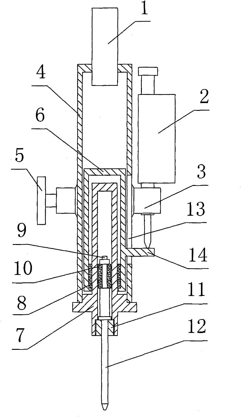
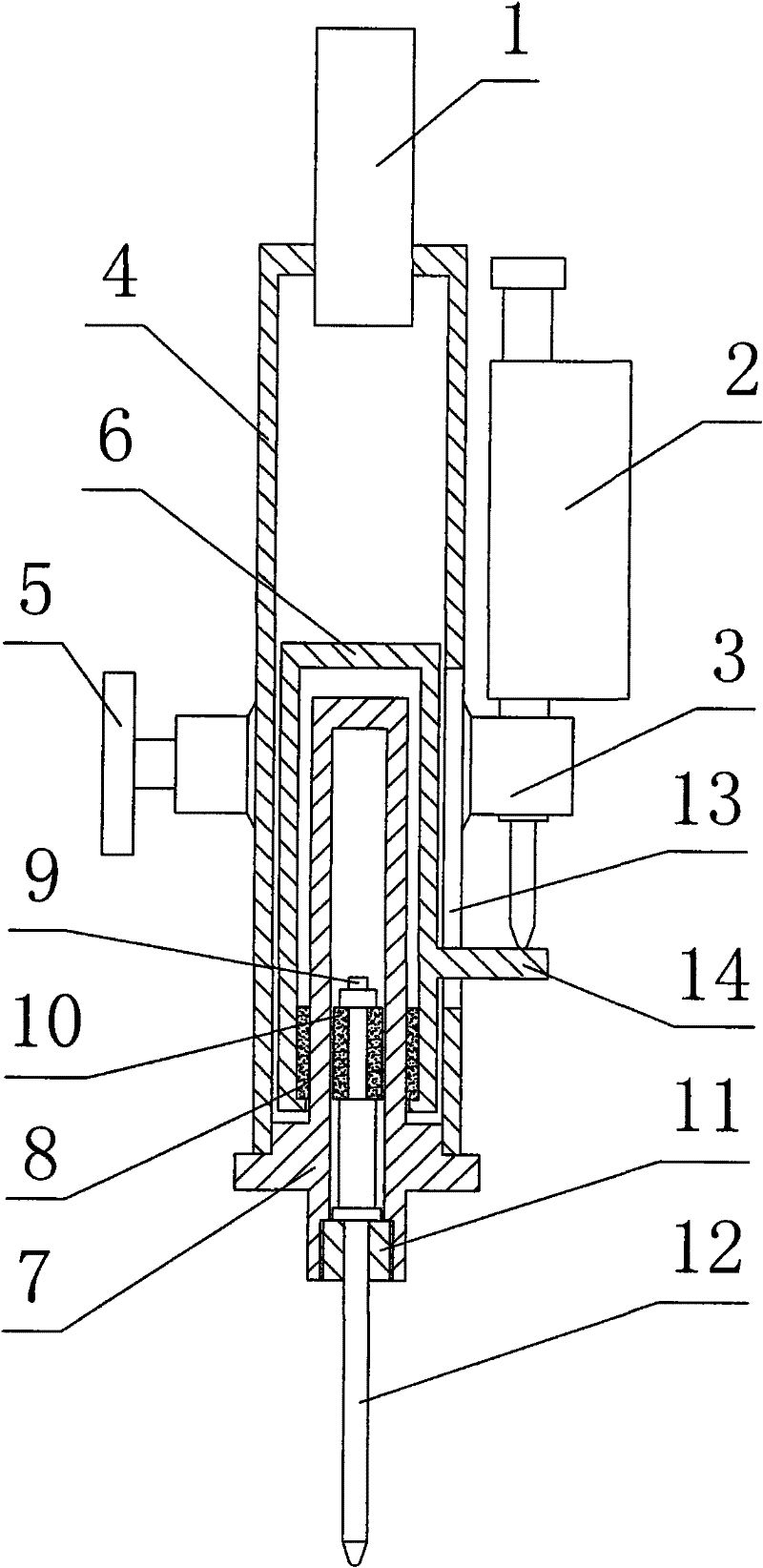
[0010] The high temperature and high pressure small length measuring device consists of a sensor 1, a dial indicator 2, a dial indicator bracket 3, a jacket 4, a compression screw 5, a movable sleeve 6, a device body 7, a high temperature magnet 8, 10, and compression nuts 9, 11 , And measuring rod 12 constitutes. Measuring rod 12 is housed in the center hole of device body 7, and measuring rod 12 is fixed by the compression nut 11 of the center hole lower end of device body 7, and the upper end of measuring rod 12 is fixed with a high temperature magnet 10 by compression nut 9. The outer cover of the device body 7 is equipped with a movable sleeve 6, and the inner wall of the movable sleeve 6 is equipped with a high-temperature magnet 8 corresponding to the high-temperature magnet 10 on the measuring rod 12. The high-temperature magnet 10 corresponds to the installation position of the high-temperature magnet 8. There is a jacket 4 on the outside, and a chute 13 is opened on ...


PUM


Abstract

The invention relates to a high-temperature and high-pressure small-size length measuring device belonging to the technical field of displacement sensor measurement and comprising a sensor, a dial gauge, a dial gauge support, an outer sleeve, a movable sleeve, a device body, high-temperature magnets and a measuring rod, wherein the measuring rod is arranged in a central hole of the device body, and the upper end of the measuring rod is provided with one high-temperature magnet; and the outer sleeve of the device body is provided with the movable sleeve, the other high-temperature magnet is arranged on the inner wall of the movable sleeve, the top of the outer sleeve is provided with the sensor, and the middle of the outer sleeve is provided with the dial gauge. The device adopts a pair ofhigh-temperature magnets for connection and interaction by magnetic force, the measuring rod is arranged in the high pressure-resistant device body, when the measuring rod is moved up and down, the high-temperature magnet on the measuring rod and the high-temperature magnet on the movable sleeve are synchronously moved up and down, and because the high-temperature magnets have no demagnetization at high temperature, the activity and the reliability of the device at high temperature and high pressure are ensured. The device solves the problem that an electronic element of the sensor generates great temperature fluctuation at high temperature and high pressure to result in inaccurate measuring precision.

Description

Technical field: [0001] The invention relates to a high-temperature and high-pressure small-sized length measuring device, which belongs to the technical field of displacement sensor measurement. Background technique: [0002] During the development of oil and gas fields, pipe sticking due to shale expansion during drilling, and leakage due to cement retention during cementing are all major production accidents. In order to avoid these production accidents, it is generally necessary to do field simulation tests in the laboratory first. Although there are many instruments that can be tested in the laboratory, the data errors of the same instrument, the same temperature and pressure, and the same test sample are large and non-repeatable, because the data errors made by the instrument are not credible. It has a great impact on scientific research and production. The main problem that causes data errors is the sensor. The sensors currently used include two general-purpose sens...

Claims


Application Information

Patent Timeline
Patent Type & Authority Patents(China)
IPC IPC(8): G01B5/02
Inventor 郭盈盈文守成张俊睿
Owner 郭盈盈
Why Eureka
Eureka Blog
Learn More