Short arc type discharge lamp
A discharge lamp, short arc technology, applied in the direction of discharge lamps, high pressure discharge lamps, discharge tubes, etc., can solve the problems of reduced illuminance, bulb breakage, etc.
- Summary
- Abstract
- Description
- Claims
- Application Information
AI Technical Summary
Problems solved by technology
Method used
Image

Examples
Embodiment 1
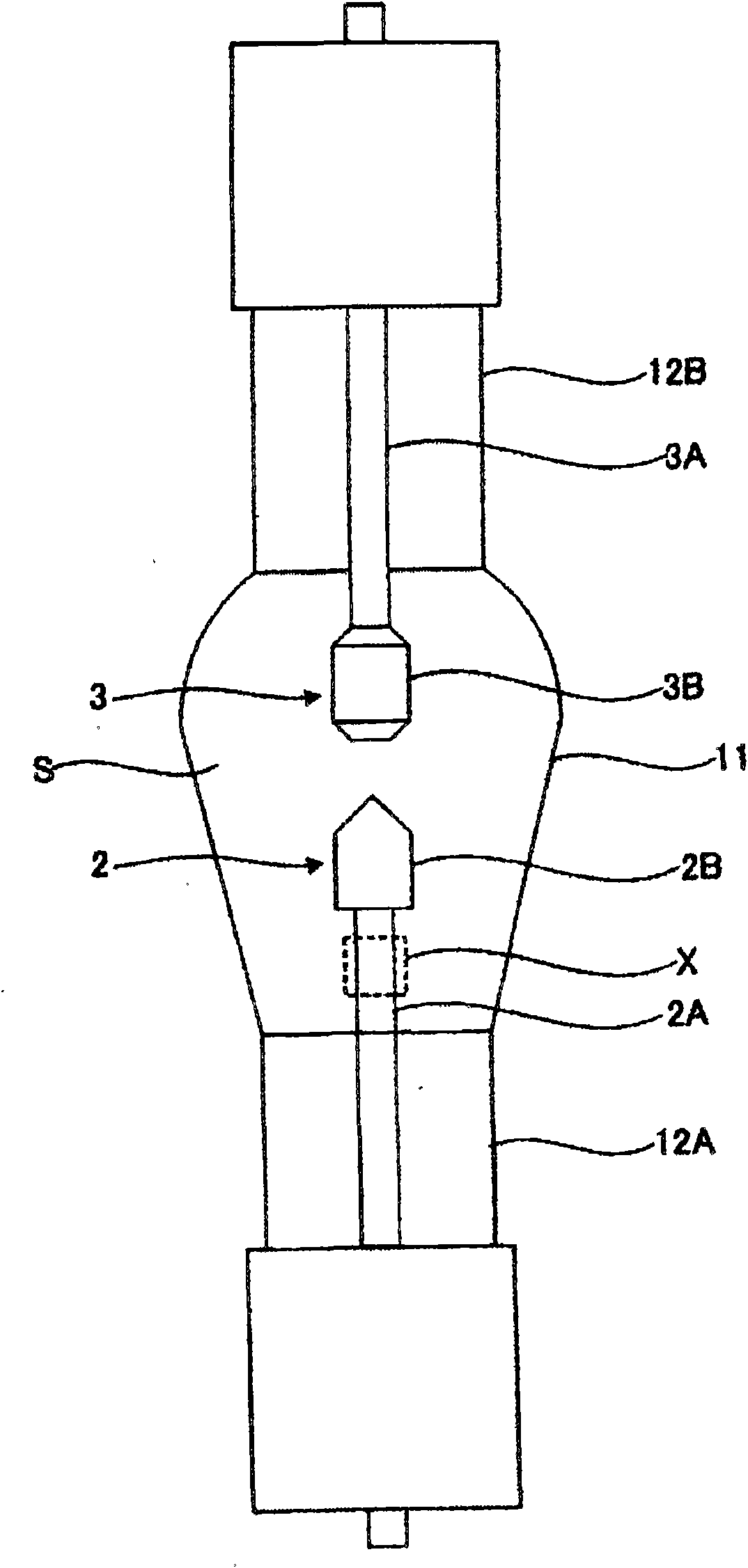
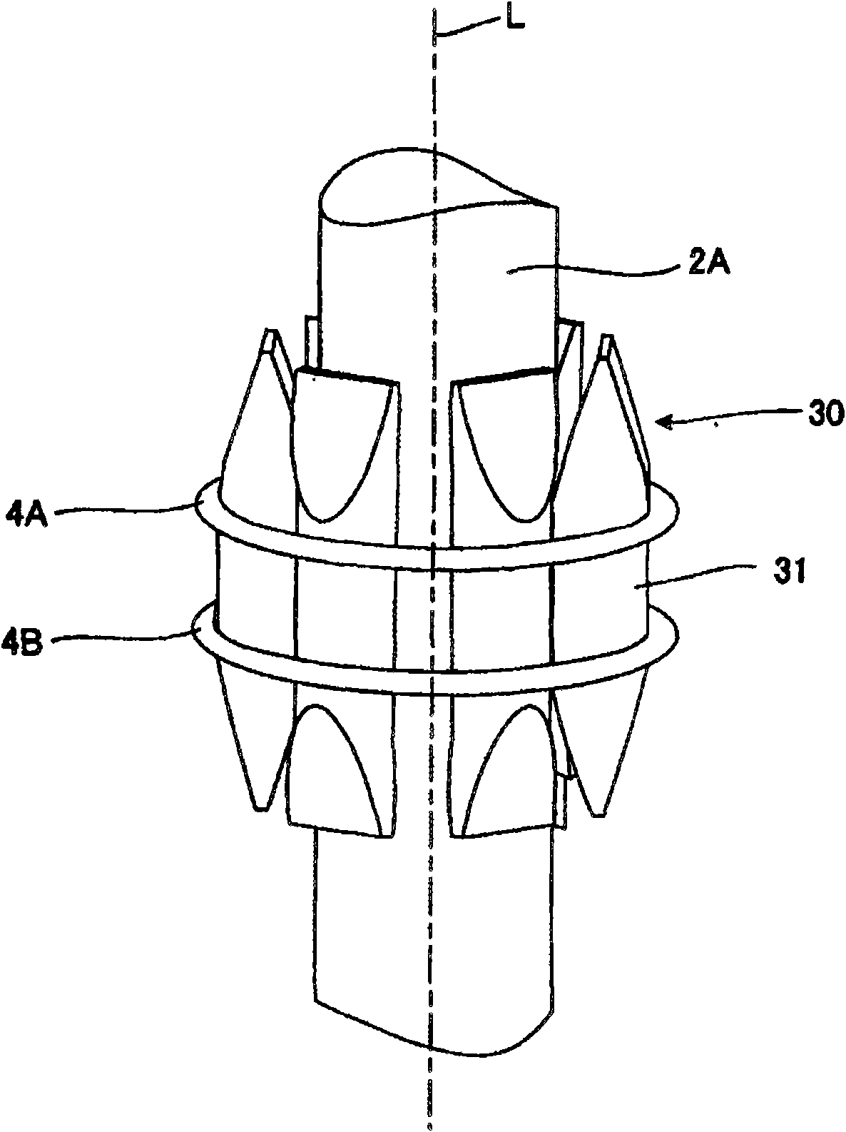
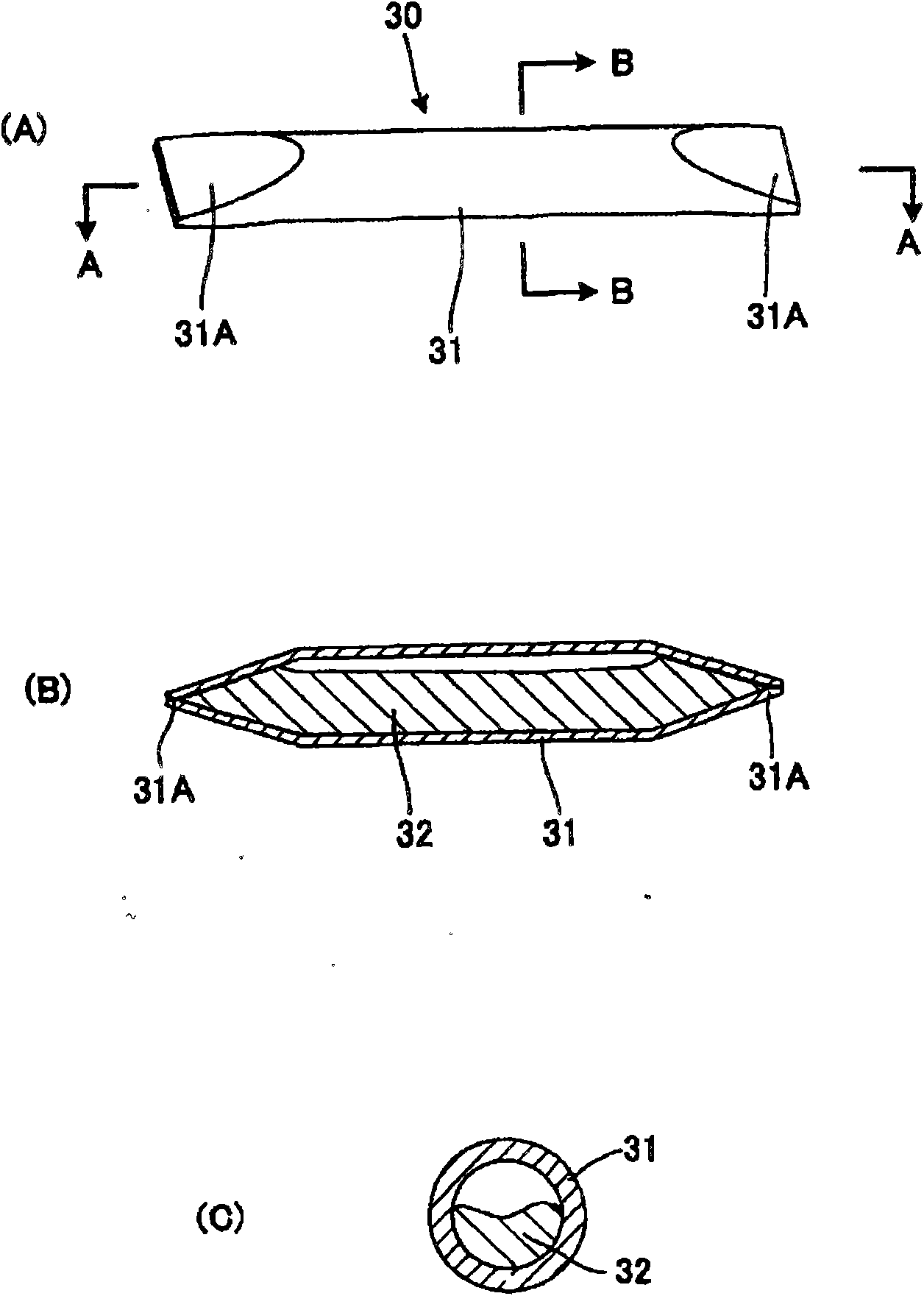
[0042] figure 2 will be figure 1 An enlarged partial explanatory diagram of part X of the short-arc discharge lamp. This figure shows the first embodiment of the structure of the shaft portion 2A and the hydrogen collector 30 fixed to the shaft portion 2A. Hereinafter, for convenience, the shaft portion 2A on the cathode 2 side will be described. image 3 It is an explanatory diagram showing the detailed structure of the hydrogen collector 30 . image 3 (A) is a perspective view of the hydrogen collector viewed obliquely, image 3 (B) is the hydrogen collector with image 3 A cross-sectional view in the longitudinal direction cut along line A-A shown in (A), image 3 (C) is the hydrogen collector with image 3 Diameter cross-sectional view taken along line B-B shown in (A).
[0043] Such as image 3 As shown, the hydrogen collector 30 is composed of a straight tube-shaped hollow container 31 made of a hydrogen-permeable metal, and a getter material 32 sealed inside t...
Embodiment 2
[0048] Figure 4 will be figure 1 An enlarged partial explanatory diagram of part X of the short-arc discharge lamp. This figure shows a second embodiment of the structure of the shaft portion 2A and the hydrogen collector 50 fixed to the shaft portion 2A. Figure 5 It is an explanatory diagram showing the detailed structure of the hydrogen collector 50 . Figure 5 (A) is a perspective view of the hydrogen collector viewed obliquely, Figure 5 (B) is the hydrogen collector with Figure 5 (A) Cross-sectional view taken along the line A-A in the width direction.
[0049] Such as Figure 5 As shown, the hydrogen collector 50 is composed of a straight tube-shaped hollow container 51 made of a hydrogen-permeable metal, and a getter material 52 sealed in the hollow container 51 . Such as Figure 5 As shown in (A), in the hollow container 51, the slope-shaped sealing portion 51A whose outer diameter gradually decreases toward the end of the hollow container 51 and the image...
Embodiment 3
[0052] Image 6 will be figure 1 An enlarged partial explanatory diagram of part X of the short-arc discharge lamp. This figure shows a third embodiment of the structure of the shaft portion 2A and the hydrogen collector 70 fixed to the shaft portion 2A. Figure 7 It is a perspective view showing the detailed structure of the hydrogen collector 70 .
[0053] Such as Figure 7 As shown, the hydrogen collector 70 has a curved tube-shaped hollow container 71 that bends a tubular member sealed with a getter material by closing both ends thereof so as to have a coil shape as a whole. The hollow container 71 has a coil inner diameter adjusted to act an elastic force on the shaft portion 2A when fixed to the shaft portion 2A.
[0054] Such as Image 6 As shown, in this embodiment, an annular concave portion 21A is formed across the entire circumference of the shaft portion 2A. Such as Image 6 As shown, the hydrogen collector 70 is fixed to the shaft portion 2A by the elastic...
PUM
 Abstract
Description
Claims
Application Information
 - R&D Engineer
- R&D Manager
- IP Professional
- Industry Leading Data Capabilities
- Powerful AI technology
- Patent DNA Extraction
Browse by: Latest US Patents, China's latest patents, Technical Efficacy Thesaurus, Application Domain, Technology Topic.
© 2024 PatSnap. All rights reserved.Legal|Privacy policy|Modern Slavery Act Transparency Statement|Sitemap