
Flat heating device

A heating device, flat plate technology, applied in electric heating devices, ohmic resistance heating, electrical components and other directions, can solve the problems of high cost, inability to uniformly heat, complex structure, etc., and achieve the effects of low cost, good heating effect and easy realization

Inactive Publication Date: 2010-09-08
DONGGUAN ANWELL DIGITAL MASCH CO LTD
View PDF5 Cites 16 Cited by
  • Summary
  • Abstract
  • Description
  • Claims
  • Application Information

AI Technical Summary

Problems solved by technology

However, there are various problems in existing substrate heating devices, such as inability to heat uniformly, or complex structure and high cost

Method used


Image

  • Flat heating device
  • Flat heating device
  • Flat heating device

Examples


Embodiment Construction

[0023] In order to describe the technical content, structural features, achieved goals and effects of the present invention in detail, the following will be described in detail in conjunction with the embodiments and accompanying drawings.

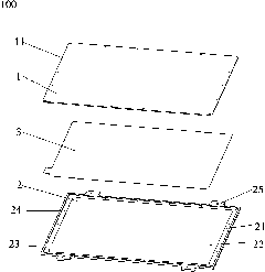
[0024] refer to figure 1 , figure 2 with image 3 The flat panel heating device 100 of the present invention comprises an upper platen 1, a lower base plate 2, and a heating sheet 3. The upper end surface of the lower base plate 2 is provided with a first installation groove 21 and a second installation groove 22 distributed in a step shape. A mounting groove 21 is matched with the upper platen 1, and the second mounting groove 22 is located in the first mounting groove 21 and matched with the heating sheet 3; the upper platen 1 is installed on the first The heating chip 3 is installed in the second installation groove 22 and is located between the upper platen 1 and the lower platen 2 .

[0025] refer to Figure 4 with Figure 5 , t...


PUM


Abstract

The invention discloses a flat heating device, comprising an upper pressure board, a lower bottom board and a heating piece, wherein, the upper end surface of the lower bottom board is provided with a first installation groove and a second installation groove which are distributed in a step shape; the first installation groove is matched with the upper pressure board; the second installation groove is arranged in the first installation groove and matched with the heating piece; the upper pressure board is installed in the first installation groove and fixedly connected with the lower bottom board; the heating piece is installed in the second installation groove and arranged between the upper pressure board and a lower pressure board; and the heating piece comprises resistance wires, an insulation film and electrodes, the resistance wires are sealed in the insulation film and are in regular bent shapes, and two ends of the resistance threads are electrically connected with a positive electrode and a negative electrode correspondingly. Compared with the prior art, the flat heating device has simple structure, low cost, easy achievement, uneasy damage, saved space and uniform heating.

Description

technical field [0001] The invention relates to a flat panel heating device, in particular to a flat panel heating device providing a surface heat source for a flat panel. Background technique [0002] OLED stands for Organic Light-Emitting Diode (Organic Light-Emitting Diode), also known as Organic Electroluminescence Display (OELD). Because of its lightness, power saving and other characteristics, it has always been favored by people in the industry. OLED display technology is different from traditional LCD display methods. It does not require a backlight, and uses very thin organic material coatings and glass substrates. When an electric current passes through, these organic materials will emit light. Moreover, the OLED display screen can be made lighter and thinner, has a larger viewing angle, and can significantly save power. It is regarded as one of the most promising products in the 21st century. [0003] However, organic light-emitting display technology still has ...

Claims


Application Information

Patent Timeline
Patent Type & Authority Applications(China)
IPC IPC(8): H05B3/30H01L51/56
Inventor 杨明生叶宗锋刘惠森范继良王勇王曼媛
Owner DONGGUAN ANWELL DIGITAL MASCH CO LTD
Learn More