
Variable case depth powder metal gear and method thereof

A surface carburizing, powder metal technology, applied in gear transmissions, belts/chains/gears, elements with teeth, etc., which can solve problems such as no indication or hint

Active Publication Date: 2010-09-08
GKN SINTER METALS GMBH & CO KG
View PDF2 Cites 6 Cited by
  • Summary
  • Abstract
  • Description
  • Claims
  • Application Information

AI Technical Summary

Problems solved by technology

[0005] However, the aforementioned patents do not indicate or imply any process by which variable case depths can be obtained in the final forged product, thereby improving performance characteristics such as increasing the load bearing capacity on the tooth flank of the gear while providing impact resistance on the tooth root and bending fatigue strength

Method used


Image

  • Variable case depth powder metal gear and method thereof
  • Variable case depth powder metal gear and method thereof
  • Variable case depth powder metal gear and method thereof

Examples


Embodiment Construction

[0017] In all figures, the same reference numerals are used to designate the same parts in each figure. Therefore, it is appropriate to refer to the respective figures at the same time. In some instances, equivalent parts in different figures may have different reference numerals for clarity.

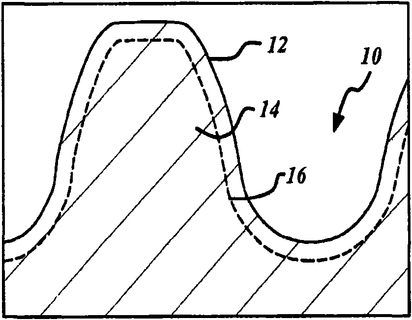
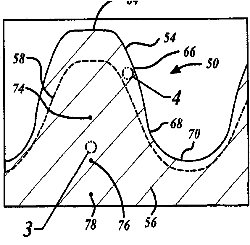
[0018] figure 2 A partial cross-sectional view of the first differential side gear 50 having a variable case depth profile 58 is shown in accordance with an embodiment of the present invention. Figure 7 It shows that according to an embodiment of the present invention, by Figure 6 made of preform 85, figure 2 A perspective view of the first differential side gear 50 of FIG.

[0019] The first differential side gear 50 includes a plurality of teeth 52 and a variable case depth profile 58 . Each tooth of the plurality of teeth 52 has a first surface 54 and a tooth core or root 56 . The first differential side gear 50 has an axis of rotation 60 wherein the teeth 52 extend radially ...


PUM

PropertyMeasurementUnit
Hardnessaaaaaaaaaa
Hardnessaaaaaaaaaa
Hardnessaaaaaaaaaa

Abstract

A gear and a method of making a forged powder metal gear having a plurality of teeth and a variable case depth profile forged in the plurality of teeth. Each tooth of the plurality of teeth has a first surface and a tooth root. A variable case depth profile is formed in each tooth of the plurality of teeth, whereby the variable case depth profile exhibits greater tooth wear resistance on the first surface and greater impact resistance in the tooth root.

Description

technical field [0001] The present invention relates to a forged powder metal part, and more particularly, to a powder metal part with variable case depth and a method of making the same. Background technique [0002] There is a continuing need for manufacturing processes that reduce cost, time and steps in producing components. Often, customer requirements to develop and improve products with superior dimensional, mechanical and / or performance characteristics first necessitate the benefits ultimately associated with improved manufacturing processes. For example, a typical differential side gear may have any or all of the following performance requirements, such as: keyway areas requiring dimensional accuracy, high shear strength, and brinelling resistance; dimensional accuracy, surface finish, and case carburization Compatible hub and thrust surfaces; gear geometries requiring dimensional accuracy, surface finish, and optimum profile; and teeth that may require impact resi...

Claims


Application Information

Patent Timeline
IPC IPC(8): B22F3/17B22F3/24B22F5/08F16H1/14F16H55/17
CPCB22F2003/247B22F2003/245B22F5/08B22F3/17F16H55/06B22F2003/175B22F2998/10B22F2999/00B22F3/02B22F3/1007B22F3/24B22F2207/11B22F2201/30B22F2207/01
Inventor T·E·格依曼
Owner GKN SINTER METALS GMBH & CO KG
Learn More