Device for storing electrical energy

A technology of saving and electrical energy, applied in the direction of circuits, electrical components, secondary batteries, etc., can solve the problems of occupation, large installation space, difficult fluid distribution, etc.

Inactive Publication Date: 2010-09-08
BEHR GMBH & CO KG
View PDF1 Cites 6 Cited by
  • Summary
  • Abstract
  • Description
  • Claims
  • Application Information

AI Technical Summary

Problems solved by technology

However, there is a problem in this arrangement, that is, it is difficult to achieve a uniform distribution of fluid in the channel
In addition, the channels for the cooling fluid take up a lot of installation space

Method used


Image

  • Device for storing electrical energy
  • Device for storing electrical energy
  • Device for storing electrical energy

Examples


Embodiment Construction

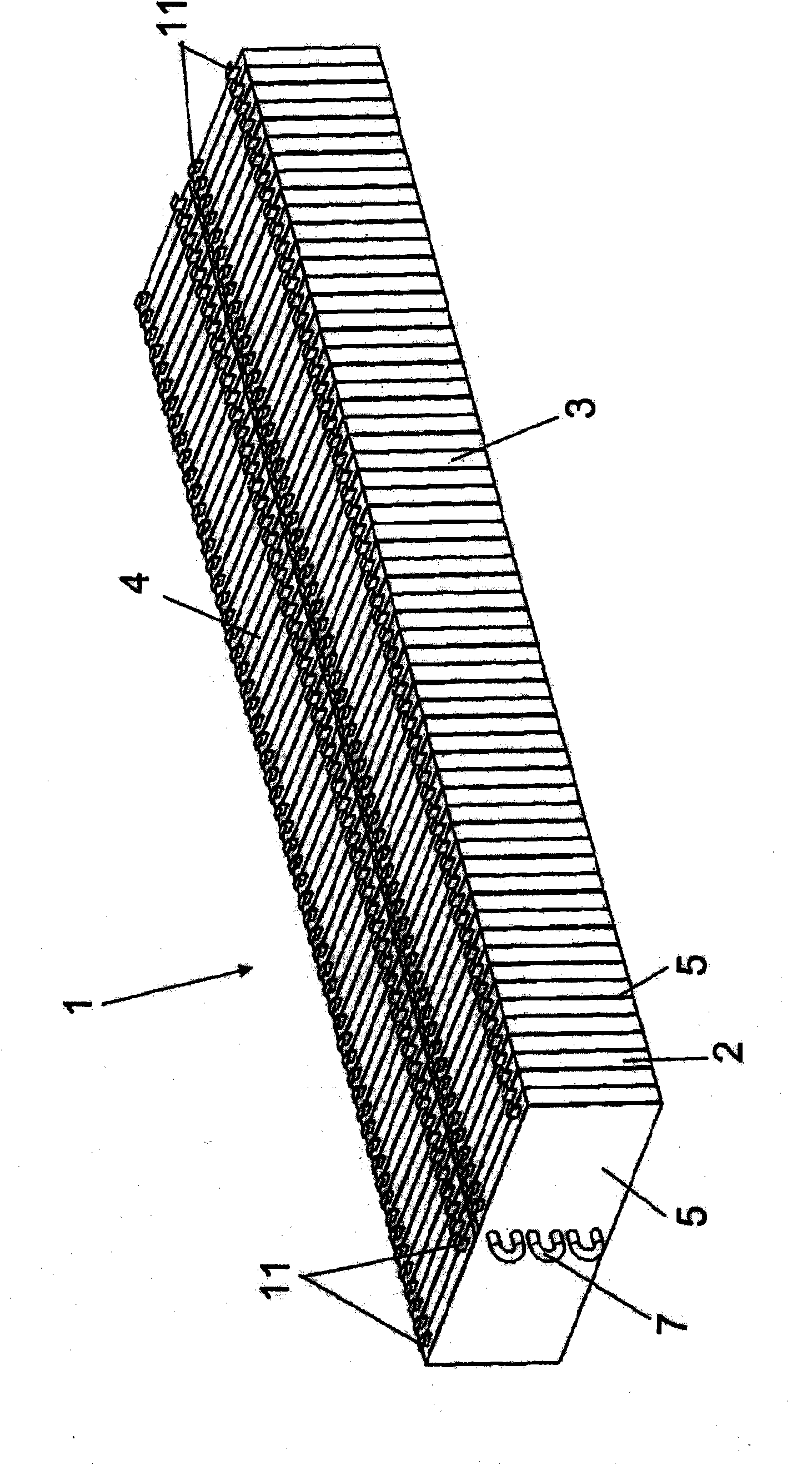
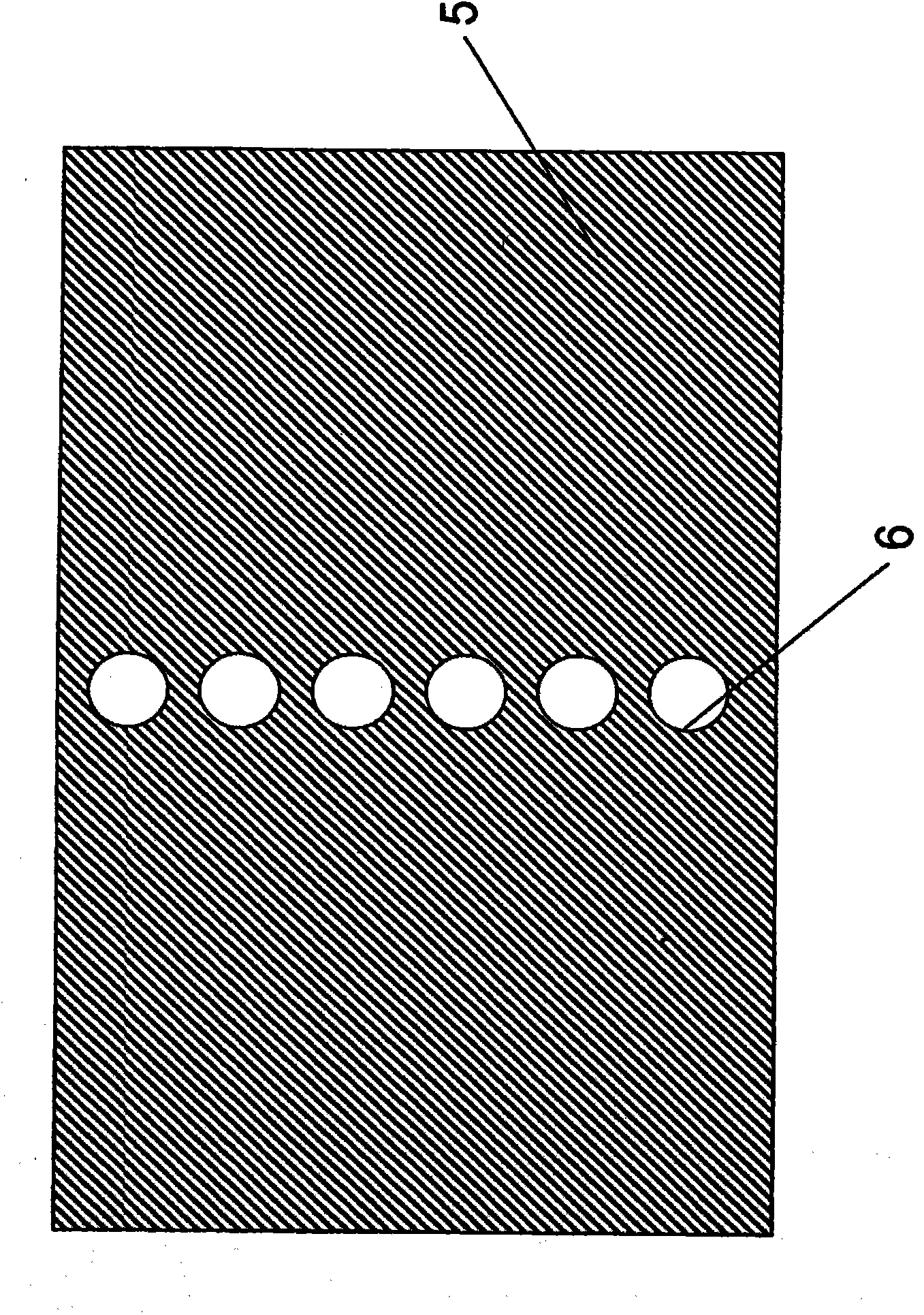
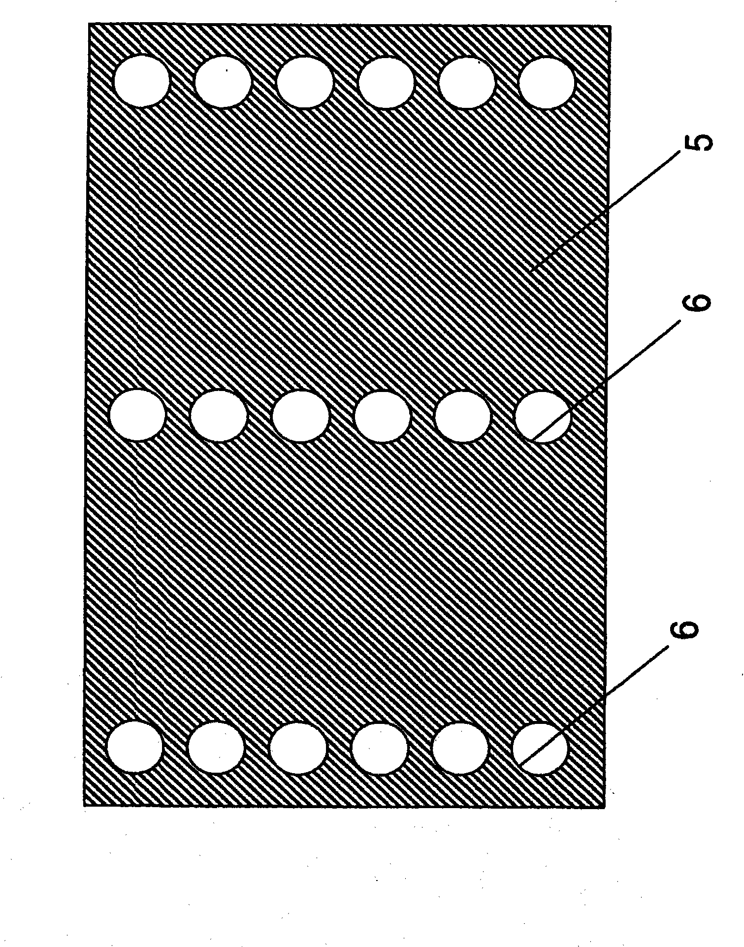
[0028] In FIG. 1 is a device 1 for storing electrical energy according to the invention. This energy storage device comprises several flat batteries 2 , for example lithium-ion flat batteries, which are stacked one above the other with their flat sides 10 and form a battery pack. According to the invention, a flat side of a flat battery 2 is a side with a larger area, which is directly or indirectly in contact with the flat side of an adjacent flat battery 2 . The first battery pack 3 and the second battery pack 4 are formed by the flat batteries and the cooling plates 5 arranged between adjacent flat batteries, each battery pack having the same number of flat batteries. Furthermore, prior to stacking, the individual flat batteries are sorted by thickness in order to provide corresponding tolerance compensation.

[0029] Here, the same cooling plate 5 is used both for the heat dissipation of the flat batteries of the first battery pack 3 and for the heat dissipation of the fl...


PUM


Abstract

The invention relates to a device for storing electrical energy (1), especially for a motor vehicle. Said device comprises a plurality of flat cells (2) that are stacked one on the other with their flat sides substantially in parallel, the flat cells defining at least one first stack (3). A cooling element (5) is arranged between adjacent flat cells of the at least one first stack. The invention is characterized in that the cooling element has at least one opening (6) into which a heat transfer element (7) is inserted.

Description

technical field [0001] The invention relates to a device for storing electric energy. Background technique [0002] Especially in the production of electric vehicles, for example hybrid vehicles, electrochemical batteries with high power density are known. Here, it refers to lithium-ion batteries. Furthermore, it is known that such high-efficiency batteries are blown through and thus cooled by the air flow, for example from the air-conditioned passenger area or directly from the air-conditioning system. [0003] It is also known to present such cells in the form of flat accumulator packs with channels between adjacent cells. These channels serve for the passage of a fluid, for example cooling liquid, so that each flat battery is cooled directly. However, there is a problem in this arrangement, that is, it is difficult to achieve uniform distribution of fluid in the channel. In addition, the channels for the cooling fluid occupy a large amount of installation space. [0...

Claims


Application Information

Patent Timeline
Patent Type & Authority Applications(China)
IPC IPC(8): H01M10/50H01M6/50H01M6/46
CPCH01M10/5004H01M10/5055H01M10/5016H01M10/5095H01M10/5032H01M6/5038F28F1/32H01M10/5053H01M6/46H01M10/625H01M10/663H01M10/647H01M10/6555H01M10/6554H01M10/613Y02E60/10
Inventor 赫伯特·达姆斯翁康拉德·普芬德尔托马斯·席赫伦马丁·施泰因巴赫卡罗琳·施密德
Owner BEHR GMBH & CO KG
Why Eureka
Try Eureka