
Device for holding head section by oil pressure of fully-automatic pipe bender

A technology of lifting device and pipe bending machine, which is applied in the field of machine head hydraulic lifting device, which can solve the problems of slow up and down movement of the machine head, increased manufacturing cost, increased weight, etc., and achieves accurate positioning of the machine head, extended Effect of service life and prevention of twisting damage

Inactive Publication Date: 2010-09-15
张家港和升数控机床制造有限公司
View PDF0 Cites 0 Cited by
  • Summary
  • Abstract
  • Description
  • Claims
  • Application Information

AI Technical Summary

Problems solved by technology

[0002] The up and down movement of the machine head of the existing automatic pipe bending machine mainly depends on the servo motor and the reducer installed on the machine head to drive the ball screw, so as to realize the up and down movement of the machine head. In the actual work process, the machine head needs to be replaced. The number of wheel molds increases the weight of the machine head, causing the ball screw to bear greater pressure, which is easy to twist and damage the ball screw. Therefore, in order to support the heavier machine head, it is necessary to replace the high-power servo motor. , this will greatly increase the manufacturing cost, the speed of the up and down movement of the machine head is also very slow, and the accuracy cannot be guaranteed

Method used


Image

  • Device for holding head section by oil pressure of fully-automatic pipe bender
  • Device for holding head section by oil pressure of fully-automatic pipe bender

Examples


Embodiment Construction

[0008] The specific content of the present invention will be described in detail below in conjunction with the accompanying drawings and specific embodiments.

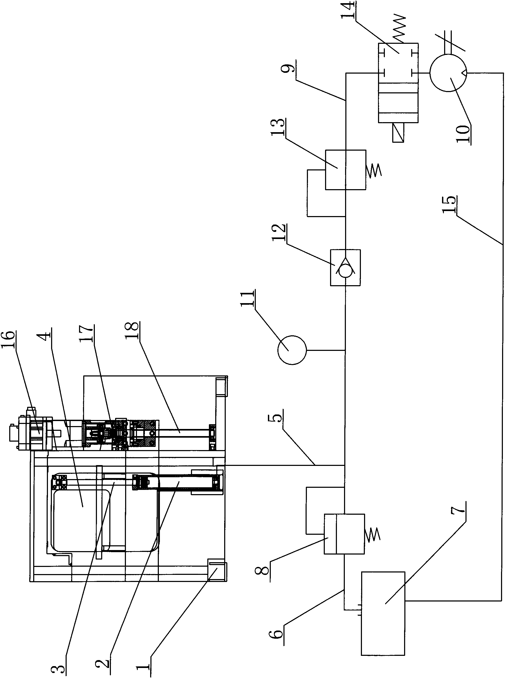
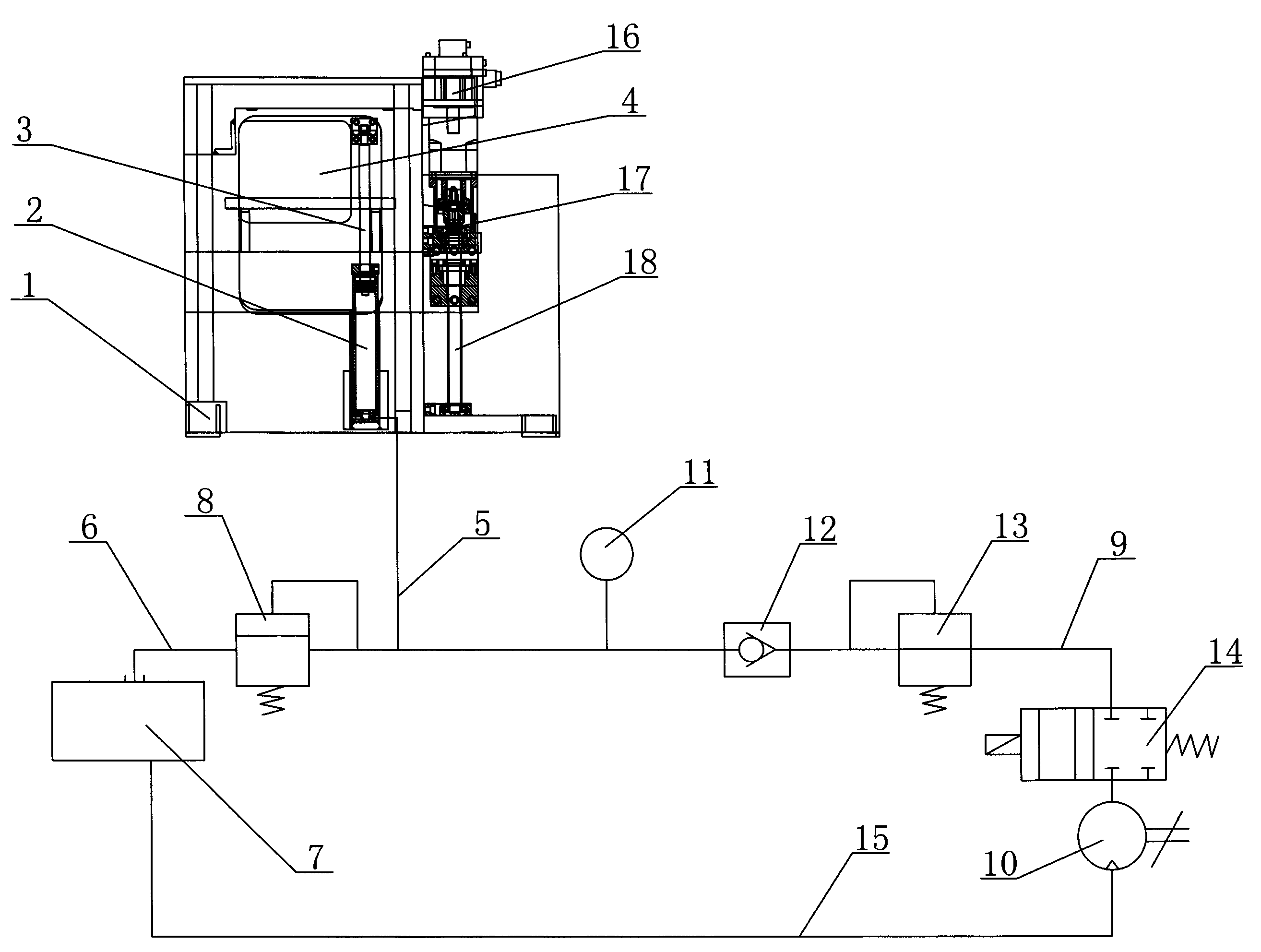
[0009] Such as figure 1 As shown, the head hydraulic lifting device in the automatic pipe bending machine includes: a jacking cylinder 2 fixedly arranged on the fuselage 1, the piston rod 3 of the jacking cylinder 2 is connected with the lower end of the machine head 4, and The lower end of the lifting oil cylinder 2 is connected with the first connecting pipe 5, and the other end of the first connecting pipe 5 is connected with one end of the oil tank 7 through the second connecting pipe 6, and an overflow valve 8 is arranged on the second connecting pipe 6, The other end of the first connecting pipe 5 is connected to the oil pump 10 through the third connecting pipe 9, and the third connecting pipe 9 is provided with a pressure gauge 11, a check valve 12, a pressure reducing valve 13 and a solenoid valve 14 in sequen...


PUM


Abstract

The invention discloses a device for holding a head section by oil pressure of a fully-automatic pipe bender, which has low manufacturing cost. The device comprises a jacking oil cylinder which is fixed on a machine body, wherein a piston rod of the jacking oil cylinder is connected with the lower end of the head section; the lower end of the jacking oil cylinder is connected with a first connecting tube; one end of the first connecting tube is connected with one end of an oil tank by a second connecting tube; an overflow valve is arranged on the second connecting tube; the other end of the first connecting tube is connected with an oil pump by a third connecting tube; a pressure gauge, a check valve, a decompression valve and an electromagnetic valve are arranged on the third connecting tube in order; and the oil pump is connected with the other end of the oil tank by a fourth connecting tube. The fully-automatic pipe bender provided with the device for holding the head section by oil pressure has the advantages of quickly realizing up-and-down motion of the head section, enabling the positioning of the head section to be more precise, ensuring that a ball screw does not bear great pressure, preventing the ball screw from being distorted and damaged, and prolonging the service life of the ball screw, along with low manufacturing cost.

Description

technical field [0001] The invention relates to a full-automatic pipe bending machine, in particular to an hydraulic head hydraulic lifting device in the full-automatic pipe bending machine. Background technique [0002] The up and down movement of the machine head of the existing automatic pipe bending machine mainly depends on the servo motor and the reducer installed on the machine head to drive the ball screw, so as to realize the up and down movement of the machine head. In the actual work process, the machine head needs to be replaced. The number of wheel molds increases the weight of the machine head, causing the ball screw to bear greater pressure, which is easy to twist and damage the ball screw. Therefore, in order to support the heavier machine head, it is necessary to replace the high-power servo motor. , This will greatly increase the manufacturing cost, and the speed of the up and down movement of the machine head is also very slow, and the accuracy cannot be g...

Claims


Application Information

Patent Timeline
Patent Type & Authority Applications(China)
IPC IPC(8): B21D7/00B21D7/16
Inventor 袁剑虹
Owner 张家港和升数控机床制造有限公司
Learn More