Pouring head of resin pouring machine

A filling head and filling machine technology, applied in the field of resin filling machines, can solve problems such as fluctuations, affecting normal work and product quality, and blocking the filling volume

Inactive Publication Date: 2012-08-29
蒋晋辉
View PDF0 Cites 0 Cited by
  • Summary
  • Abstract
  • Description
  • Claims
  • Application Information

AI Technical Summary

Problems solved by technology

Resin usually has considerable viscosity and is easy to solidify. It is pushed by the piston in the cylinder through the opening at the front end of the cylinder—after the pouring port is pushed out, there is often sticky residue on the inner wall of the cylinder, especially the pouring port. If it is not cleaned in time, it will be cured. Cause blockage and fluctuation of perfusion volume, affect normal work and product quality, and in severe cases, the perfusion head has to be replaced, which brings great trouble and is a problem that has not been effectively solved for a long time

Method used


Image

  • Pouring head of resin pouring machine
  • Pouring head of resin pouring machine
  • Pouring head of resin pouring machine

Examples


Embodiment Construction

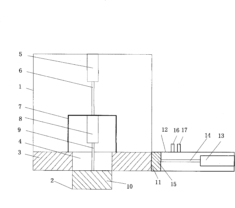
[0049] The first embodiment of the present invention is such as Figure 1~6 shown. include:

[0050] ——The perfusion cylinder 1 is a large cylinder with a vertical axis;

[0051] ——The filling port 2 is a small cylinder connected to the bottom of the filling cylinder 1 and on the same axis;

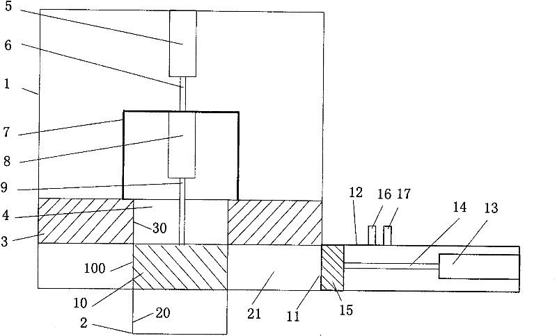
[0052] ——The large piston 3 located in the perfusion cylinder 1 and on the same axis, the large piston 3 is a circular column with an inner cylindrical cavity 4, and its outer cylindrical surface is close to the inner wall cylindrical surface of the perfusion cylinder 1, and the inner cylinder The surface 30 is flush with the inner wall cylindrical surface 20 of the filling port 2 (see image 3 );

[0053] ——The small piston 10 is cylindrical, and its outer cylindrical surface 100 abuts against the inner cylindrical surface 30 of the large piston 3 or / and the inner wall cylindrical surface 20 of the filling port 2 (see image 3 );

[0054] ——Along the axis, the first power slide rod...


PUM


Abstract

The invention discloses a pouring head of a resin pouring machine, which comprises a feeding device and a pouring cylinder in which a piston is arranged. A material fed into the cylinder from the feeding device is pushed by the piston and discharged from a pouring port. The pouring head is characterized in that: the pouring port is in the axial direction in which the piston moves; a section of straight cylinder of which the cross section is shrunk is connected at one end of the forwarding direction of the pouring cylinder; and a small piston is arranged in the straight cylinder. The pouring head has the following action steps that: both the piston and the small piston are retracted back; both the piston and the small piston go forward at the same time until getting to the end part of the pouring cylinder; and the small piston continuously goes forwards until getting to an outlet of the straight cylinder. The design can effectively improve the resin residual condition of the pouring head of the resin pouring machine and solves the problems that blockage and fluctuation of grouting amount caused by untimely cleaning of residual resin affect normal work and product quality.

Description

technical field [0001] The invention relates to a resin potting machine for manufacturing such as resin potting capacitors, in particular to the structure and action process of its potting head, which belongs to B29C41 / 34 in the international patent classification table. Background technique [0002] The traditional resin potting machine used to manufacture metal film capacitors sends the resin pre-mixed with curing agent into a cylindrical potting head with a built-in piston and then pours it into the workpiece. The resin usually has considerable viscosity and is easy to solidify. It is pushed by the piston in the cylinder through the opening at the front end of the cylinder—after the filling port is pushed out, there is often sticky residue on the inner wall of the cylinder, especially the filling port. If it is not cleaned in time, it will be cured. It causes blockage and fluctuations in perfusion volume, which affects normal work and product quality. In severe cases, the...

Claims


Application Information

Patent Timeline
Patent Type & Authority Patents(China)
IPC IPC(8): B29C39/22
Inventor 蒋晋辉
Owner 蒋晋辉
Why Eureka
Try Eureka