Supercharge Your Innovation With Domain-Expert AI Agents!

Engine assembly with valve seat vent passages and method of forming

A technology of engine and valve seat, applied in the direction of engine components, combustion engines, machines/engines, etc.

Inactive Publication Date: 2010-09-15
GM GLOBAL TECH OPERATIONS LLC
View PDF5 Cites 7 Cited by
  • Summary
  • Abstract
  • Description
  • Claims
  • Application Information

AI Technical Summary

Problems solved by technology

However, the use of these modified valve seat inserts required extensive modification of the molds used in the manufacture of conventional inserts or required additional costly machining of existing inserts

Method used


Image

  • Engine assembly with valve seat vent passages and method of forming
  • Engine assembly with valve seat vent passages and method of forming
  • Engine assembly with valve seat vent passages and method of forming

Examples


Embodiment Construction

[0043] Examples of the invention will now be described more fully with reference to the accompanying drawings. The following description is merely exemplary in nature and is not intended to limit the invention, its application or uses.

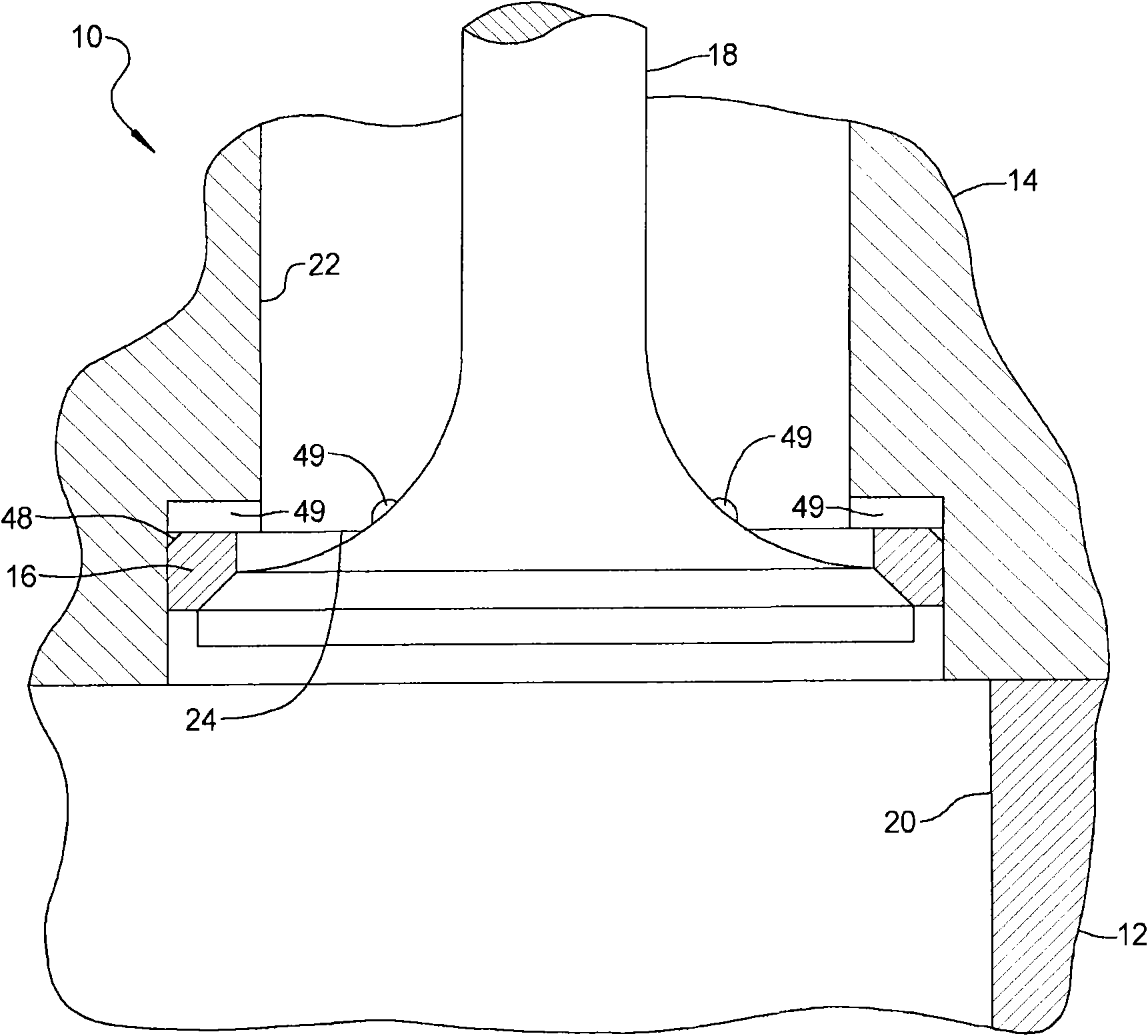
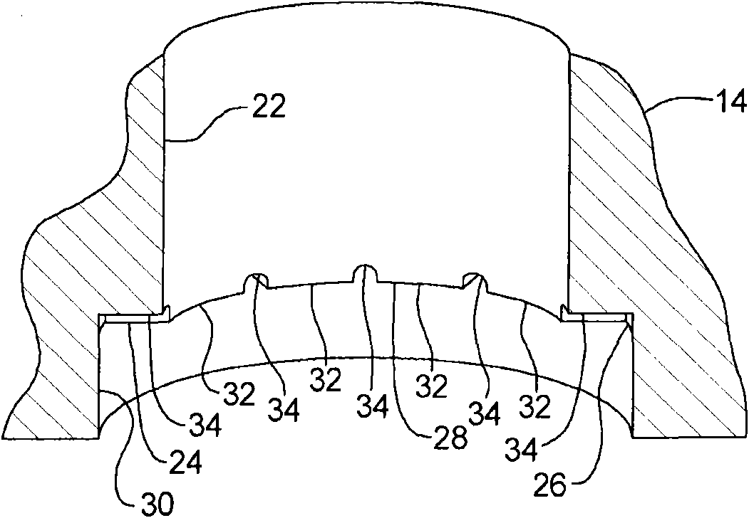
[0044] refer to Figure 1-4 , the engine assembly 10 may include an engine block 12 , a cylinder head 14 , a valve seat insert 16 and a valve 18 . The engine block 12 may define a cylinder bore 20 . Cylinder head 14 may be secured to engine block 12 and may define intake ports 22 and valve seats 24 .

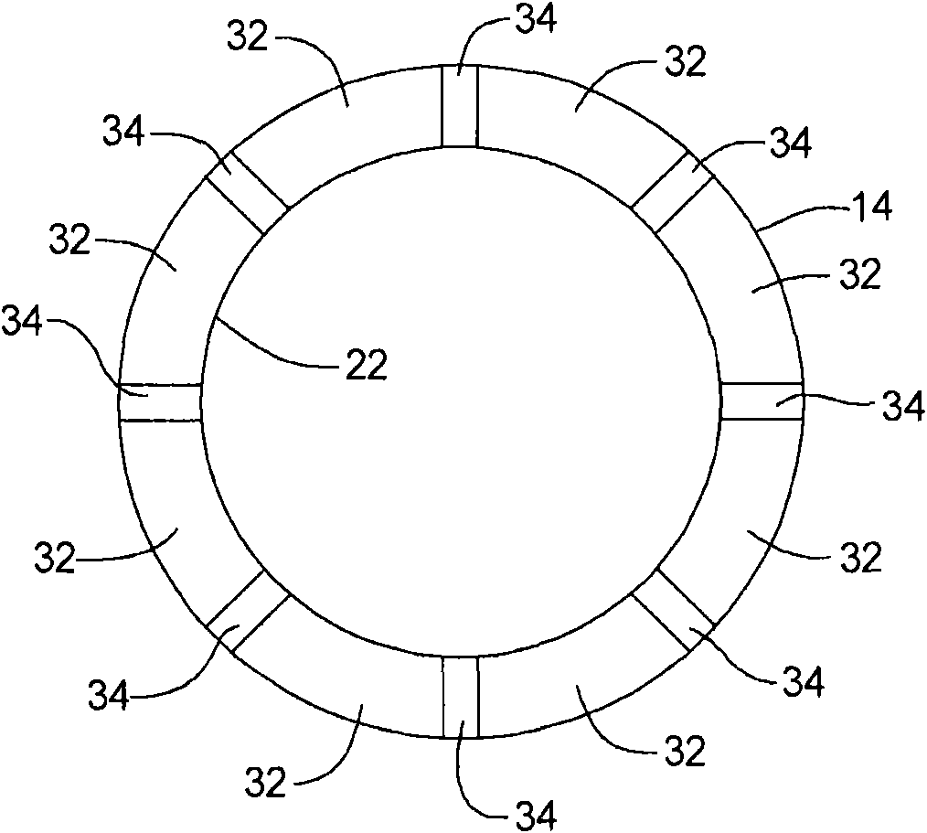
[0045] The valve seat 24 may be defined as an outlet of the intake port 22 and may include a stepped region 26 . The stepped region 26 may include an axial end surface 28 , an inner radial surface 30 , a raised portion 32 and a recessed portion 34 . The cylinder head features discussed above may be integrally formed as a single casting. Alternatively, the raised portion 32 and the recessed portion 34 may be formed in the cylinder head 14 af...


PUM


Abstract

The present invention relates to an engine assembly with valve seat vent passages and a method of forming the same. Concretely, the engine assembly may include an engine block defining a cylinder bore, a cylinder head fixed to the engine block, and a valve seat insert. The cylinder head may include an intake port, defining an inlet in fluid communication with an air source and an outlet in fluid communication with the cylinder bore. The valve seat may be defined at the outlet of the intake port and may include a stepped region. The stepped region may define a seating surface extending radially outward from the intake port. The seating surface may include a series of protrusions circumferentially spaced from one another around the outlet and forming a series of recesses therebetween. The valve seat insert may be located within the stepped region and may include a first axial end surface abutting the protrusions on the seating surface.

Description

technical field [0001] The present invention relates to air intake ports for engine cylinder heads. Background technique [0002] This section provides background information related to the present disclosure which is not necessarily prior art. [0003] The engine assembly may include a cylinder head defining an intake port having a valve seat insert disposed therein. The interface between the valve seat insert and the cylinder head may include a small gap, allowing fuel to be introduced during an injection event. This small gap traps fuel between the valve seat insert and the cylinder head. In engines burning fuel containing a higher percentage of ethanol, this trapped fuel can lead to corrosion of the cylinder head. One solution to this problem is to form channels in the valve seat insert. However, the use of these modified valve seat inserts requires either extensive modification of the molds used in the manufacture of conventional inserts or additional costly machini...

Claims


Application Information

Patent Timeline
IPC IPC(8): F02F1/42F02F1/24
CPCF01L3/06Y02T10/146F01L3/22F01L2103/00F01L2303/00Y02T10/12Y10T29/49298Y10T29/493Y10T29/49306
Inventor E·P·贝克D·L·穆尔
Owner GM GLOBAL TECH OPERATIONS LLC
Features
  • R&D
  • Intellectual Property
  • Life Sciences
  • Materials
  • Tech Scout
  • Unparalleled Data Quality
  • Higher Quality Content
  • 60% Fewer Hallucinations
Learn More