Measuring method for on-site detection of thermal resistance of enclosing structure
An enclosure structure, on-site detection technology, applied in the direction of material thermal development, material thermal conductivity, etc., can solve problems such as thermal resistance detection error, and achieve the effect of reducing influence and error.
- Summary
- Abstract
- Description
- Claims
- Application Information
AI Technical Summary
Problems solved by technology
Method used
Image

Examples
Embodiment Construction
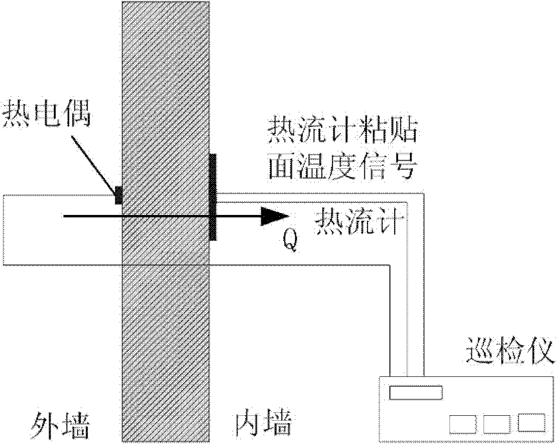
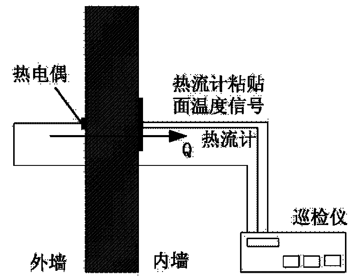
[0012] The present invention will be described in further detail below in conjunction with the accompanying drawings.
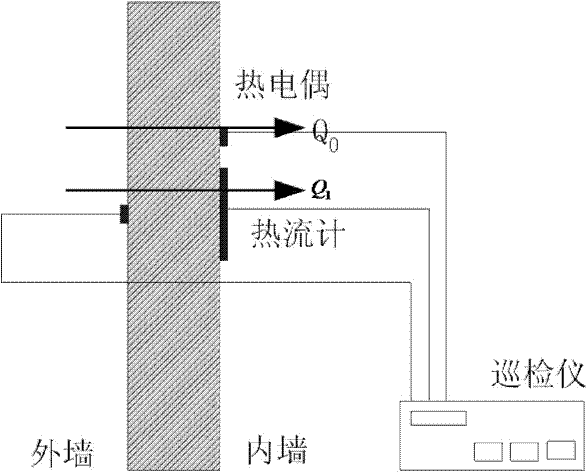
[0013] see figure 2 , in view of the error produced in the process of field testing of the existing heat flow meter method, the present invention will use the temperature of the heat flow meter and the wall pasting surface to be extracted during the test, that is, the temperature signal of the heat flow meter pasting surface to replace the original temperature of the wall surface near the heat flow meter, so that The measured heat flow corresponds to the temperature difference, so in the case of one-dimensional heat transfer at the test site, the calculation of thermal resistance will not be affected. The calculation formula in steady state is: R=ΔT / Q, ΔT is the temperature of the inner surface The temperature difference with the outer surface, Q is the heat flow of the heat flow meter reaction.
[0014] During installation, install the thermocouples on the...
PUM
 Abstract
Description
Claims
Application Information
PatSnap Eureka turns technology decisions into work you can execute. Powered by our Innovation Knowledge Graph, it runs expert workflows across engineering, life sciences, materials and intellectual property. Get your review-ready output in minutes.


