Covered wire cold connector

A technology of leather wires and connecting tubes, which is applied in the coupling of optical waveguides, etc., can solve the problems of maintenance of insertion loss, clean drainage, and no consideration of air, etc., and achieve simple structure, reduce loss value, and improve reliability and stability. Effect

Inactive Publication Date: 2010-09-15
无锡光太光通讯器件有限公司
View PDF5 Cites 8 Cited by
  • Summary
  • Abstract
  • Description
  • Claims
  • Application Information

AI Technical Summary

Problems solved by technology

Many companies only consider adding matching liquid at the breakpoint to isolate the air in product design, but do not consider how to remove the existing air at the breakpoint. Wrapped up, the insertion loss is maintained at around 0.5

Method used


Image

  • Covered wire cold connector
  • Covered wire cold connector
  • Covered wire cold connector

Examples


Embodiment Construction

[0017] The present invention will be further described below in conjunction with specific drawings and embodiments.

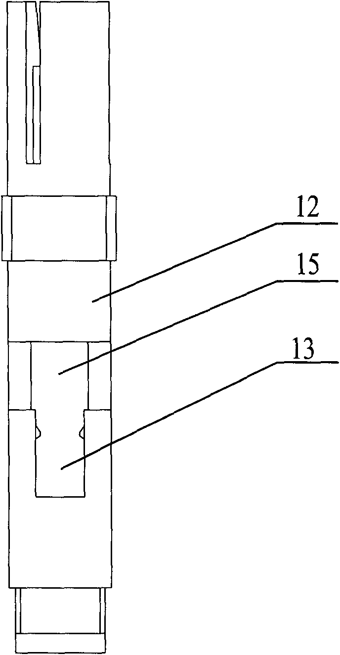
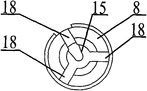
[0018] Such as Figure 1 to Figure 6 As shown: the present invention includes a boot 1, a crimping groove 2, a crimping twist 3, a ferrule pusher 4, a first ferrule tail handle 5, a connecting through hole 6, a first ferrule 7, and a first ferrule cavity 8. Vent hole 9, connecting pipe 10, second ferrule 11, second ferrule cavity 12, installation groove 13, second ferrule tail handle 14, positioning groove 15, crimping hole 16, connecting hole 17, The first dividing groove 18 , the second dividing groove 19 , the first slot 20 and the second slot 21 .

[0019] Such as figure 1 As shown: one end of the first ferrule cavity 8 is provided with a groove; one end of the second ferrule cavity 12 is embedded in the groove of the first ferrule cavity 8, and is connected with the first ferrule cavity The cavity 8 is tightly connected; the first ferrule cavity 8 commu...


PUM


Abstract

The invention relates to a covered wire cold connector, which comprises a first plug core cavity and a second plug core cavity, wherein a first plug core tail handle is arranged in the first plug core cavity; one end of the first plug core tail handle is provided with a first plug core, while the other end is provided with a first slot; the first plug core is extended into a connecting pipe corresponding to the other end connected with the first plug core tail handle; the connecting pipe is provided with a second plug core corresponding to the other end provided with the first plug core; the second plug core is provided with a second plug core tail handle corresponding to the other end embedded in the connecting pipe; the second plug core tail handle is provided with a second slot corresponding to the other end provided with the second plug core and penetrates into a second plug core cavity; an optical fiber matching fluid corresponding to the end part of the first plug core is arranged in the connecting pipe and surrounds the end part of the first plug core; and the connecting pipe is provided with a vent hole corresponding to a side wall provided with the optical fiber matching fluid. The covered wire cold connector has the advantages of simple structure, convenient operation, low splice loss, high stability and high reliability.

Description

technical field [0001] The invention relates to a cold splicer, in particular to a covered wire cold splicer, which belongs to the technical field of optical fiber splicing. Background technique [0002] In the field of optical fiber splicing, mechanical optical fiber splicing and fusion splicing are two different ways to achieve fixed connection of optical fibers. Fiber-to-the-home deployment at user premises and indoor fiber connection points has the characteristics of a large number of users and scattered locations. Due to the different installation time of different users, the same community, similar ADSL service is opened. When the user reaches a certain level, the existing construction personnel and fusion splicing machines cannot meet the time requirements for the user to open the service. Due to the characteristics of simple operation, short personnel training period, and small tool investment, the mechanical optical fiber splicing method provides the most cost-eff...

Claims


Application Information

Patent Timeline
Patent Type & Authority Applications(China)
IPC IPC(8): G02B6/38
Inventor 庄敏霞李学准
Owner 无锡光太光通讯器件有限公司
Why Eureka
Try Eureka