Touch display device and touch device

A technology of a touch display device and a touch device, which is applied to instruments, electrical digital data processing, and the input/output process of data processing. The effect of measuring sensitivity

Inactive Publication Date: 2010-09-15
AU OPTRONICS CORP
View PDF0 Cites 43 Cited by
  • Summary
  • Abstract
  • Description
  • Claims
  • Application Information

AI Technical Summary

Problems solved by technology

However, in order to enhance the capacitive sensing signal and avoid delay or failure of the sensing signal, the electrode design of the traditional projected capacitive touch technology still has room for improvement. How to improve the detection precision of the touch device is still a challenge. A major topic in the field of touch

Method used


Image

  • Touch display device and touch device
  • Touch display device and touch device
  • Touch display device and touch device

Examples


Embodiment

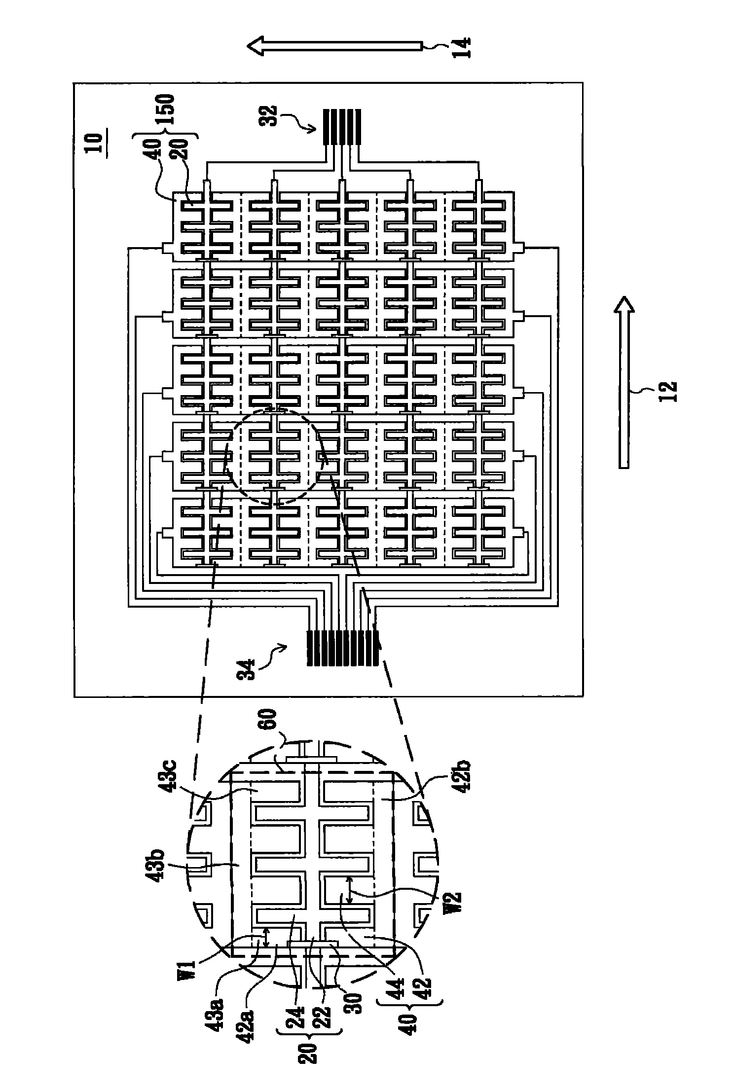
[0039] Such as figure 1As shown, the touch sensing element 150 is disposed on the substrate 10 , including the sensing electrodes 20 , the driving electrodes 40 , the first connection line 32 of the first circuit, the second connection line 34 of the second circuit and the bridge line 30 . The touch sensing element 150 can be a capacitive touch device, such as a projected capacitive touch matrix structure, especially a mutual type projected capacitive touch matrix structure. The sensing electrodes 20 and the driving electrodes 40 are composed of two different sets of electrodes, which are respectively connected to the first connection line 32 of the first circuit and the second connection line 34 of the second circuit. Wherein, each sensing electrode 20 can be arranged parallelly on the substrate 10 substantially along the first direction 12 , and each driving electrode 40 can be arranged parallelly on the substrate 10 substantially along the second direction 14 . The first d...


PUM


Abstract

The invention provides a touch display device and a touch device. The touch display device comprises a display panel and a touch sensing element arranged on the display panel, wherein the touch sensing element comprises sensing electrodes and drive electrodes, the sensing electrodes are arranged in the first direction, the drive electrodes are arranged in the second direction, and the sensing electrodes and the drive electrodes are interlaced with each other to form a plurality of capacitor sensing units; each sensing electrode comprises a principal electrode bar and a plurality of electrode branches connected to the principal electrode bar; the drive electrode in each capacitor sensing unit comprises at least one peripheral electrode bar and at least one inside electrode bar which are interlaced with the electrode branches of the sensing electrode; and each peripheral electrode bar has a first width, the inside electrode bar has a second width in the first direction, and the first width is less than the second width.

Description

technical field [0001] The present invention relates to a touch device, and in particular to a capacitive touch device. Background technique [0002] At present, the commonly used touch technologies for electronic devices are: resistive, surface capacitive, projected capacitive, surface acoustic wave, optics imaging, infrared ( infrared), refraction (bendingwave) and digital conversion (active digitizer), etc. The first three technologies are suitable for smaller portable devices or consumer electronic products because of their small size and relatively high precision. [0003] As far as resistive touch technology is concerned, there are technical limitations in physical conditions from touching the screen to touch detection, data calculation and position confirmation. For example, contact detection will cause excessive wear and tear in some specific areas due to the constant contact range, which will reduce the conduction efficiency of the conductive film contact. In add...

Claims


Application Information

Patent Timeline
IPC IPC(8): G06F3/044
CPCG06F3/0443G06F3/0446G06F3/0448G06F2203/04111
Inventor 谢明伦刘柏源
Owner AU OPTRONICS CORP
Why Eureka
Try Eureka