Magnetic suction socket and combination socket

A combined socket and magnetic attraction technology, applied in coupling devices, electrical components, circuits, etc., can solve the problems of easy movement obstacles and failures, inability to expand at will, and complex socket structure, so as to avoid the clutter of multi-socket wiring, Quick and easy combination, compact effect

Inactive Publication Date: 2012-05-30
宁振江
View PDF0 Cites 1 Cited by
  • Summary
  • Abstract
  • Description
  • Claims
  • Application Information

AI Technical Summary

Problems solved by technology

The setting of the movable plate mechanism in the socket makes the structure of the socket complex, prone to movement obstacles and failures, and has safety problems in use
In addition, the existing ordinary plug-in socket boards have a certain number of sockets and cannot be expanded at will, which is inconvenient to use.

Method used


Image

  • Magnetic suction socket and combination socket
  • Magnetic suction socket and combination socket
  • Magnetic suction socket and combination socket

Examples


Embodiment 1

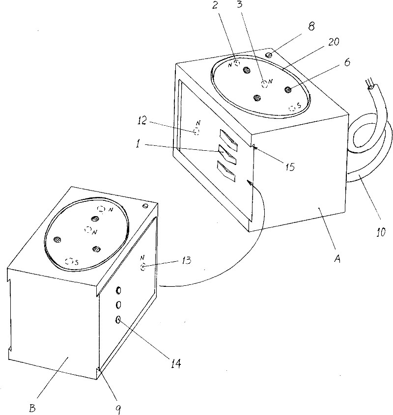
[0021] Embodiment 1: The magnetic suction socket of the present invention is described by taking a two-phase three-head socket as an example.

[0022] Such as figure 1 , figure 2 As shown, three socket contacts 6 arranged in a triangular shape are fixed on the panel of a rectangular or cubic socket housing 4 (the three contacts can also be arranged vertically, horizontally or obliquely in a straight line), and the upper part One of them is the zero line contact, and the two lower ones are respectively used as the live line contact and the ground line contact. The panel bottom surface of socket housing 4 is fixed with two socket magnets 2 (three also can be set), and the setting polarity of two socket magnets 2 is opposite, and is separately located at the axis line two ends on socket housing 4 panels, In this way, when removing the plug, it is convenient to lift the inner end of the plug first and then remove the plug as a whole by manual operation.

[0023] figure 1 Amon...

Embodiment 2

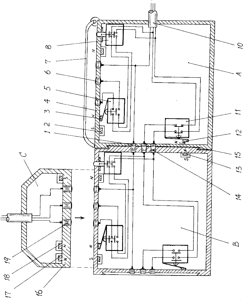
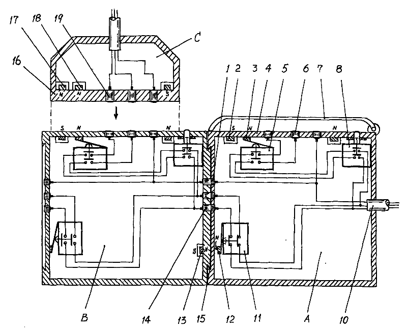
[0030] Embodiment 2: The combined socket of the present invention is illustrated by taking the parallel connection of a first socket A with two phases and three pins and a second socket B with two phases and three pins as an example.

[0031] Such as figure 1 As shown, both the first socket A and the second socket B are formed by adding a bypass branch on the basis of the magnetic attraction socket of the present invention. Wherein, the first socket A is the basic socket of the combination socket of the present invention, and the second socket B is the connection socket of the combination socket of the present invention. It can also be expanded arbitrarily on the left side of the connection socket, and several second sockets can be added.

[0032] Such as figure 1 , figure 2 As shown, the first socket A is fixed with three socket contacts 6 (a fire wire contact, a ground wire contact and a neutral wire contact) and two pull-in plugs on the panel of the socket housing 4. S...


PUM


Abstract

The invention relates to a magnetic suction socket and a combination socket. In the magnetic suction socket, a socket contact and a socket magnet are fixed on the panel of a socket housing, a contact switch and a control switch are installed in the socket housing, the socket contact and the contact switch are electrically connected, the control end of the contact switch is provided with a movablepush magnet, the control switch is respectively connected between connecting wires of a power wire inlet end and the contact switch, and the power wire inlet end is arranged on a side panel of the socket housing. The combination socket is formed by adding one bypass circuit between a first socket and a second socket on the basis of the magnetic suction socket, wherein the bypass circuit is formedby connecting the power wire inlet end, a bypass switch and a bypass output contact, and the on and off of the bypass switch is controlled by a fixed push magnet relatively arranged in the adjacent second socket. Thus, the random extension of the combination socket is realized. The combination socket is especially applicable to internet bars, exhibitions and other places which use electric appliances in a centralized way.

Description

technical field [0001] The invention relates to an electric connection device with coordinated action of two parts, in particular to a magnetic attraction socket and a combination socket. Background technique [0002] Ordinary plug-in plugs and sockets, if the fit is too loose, will cause poor contact, contact arcing, oxidation, etc.; if the fit is too tight, it will cause difficulty in plugging and unplugging. In order to solve these defects in structure and use, several patents of magnetically-attached plugs and sockets have been retrieved in the Chinese patent database. This type of magnetic plug and socket is attracted by the magnets on the plug and the socket, so that the electrical contacts on the panels of the two are kept in close contact. At the same time, a movable plate mechanism set in the socket operates to connect the socket contacts. The connection line, so that the power is conducted through the socket to the plug. The arrangement of the movable plate mecha...

Claims


Application Information

Patent Timeline
Patent Type & Authority Patents(China)
IPC IPC(8): H01R13/639H01R13/70H01R25/00H01R13/514
CPCH01R13/7037H01R27/02H01R13/7038H01R13/6205
Inventor 宁振江
Owner 宁振江
Why Eureka
Try Eureka