Composite vertical compression mould clamping device

A mold clamping device and a composite technology, applied in the field of mold clamping devices, can solve the problems of not being too large in mold opening stroke, large machine length and weight, unable to meet product requirements, etc. , the effect of large bearing capacity

Active Publication Date: 2010-09-22
HAITIAN PLASTICS MACHINERY GRP
View PDF3 Cites 9 Cited by
  • Summary
  • Abstract
  • Description
  • Claims
  • Application Information

AI Technical Summary

Problems solved by technology

[0002] In the existing injection molding machine industry, the link type mold clamping device occupies the main position. Its structure is generally composed of the head mold, the second plate and the tail plate. The head mold and the second plate are opened and closed through the linkage mechanism. The defect is 1. For a machine with a certain tonnage, the mold opening stroke should not be too large due to structural restrictions
For some products with deep cavities, this kind of machine cannot meet the requirements of the products.
2. The connecting rod mechanism is more complicated. When the tonnage of the machine is relatively large, the length and weight of the machine are relatively large, which also increases the cost accordingly
[0005] Although the above-mentioned two-plate mold clamping mechanism has many advantages, since the second plate of the clamping device is set on the pull rod and slides on the pull rod, the pull rod is affected by the pulling force of the second plate and the lateral gravity of the mold assembly fixed on the second plate. It is easy to deform, so it will affect the movement of the second board

Method used


Image

  • Composite vertical compression mould clamping device
  • Composite vertical compression mould clamping device
  • Composite vertical compression mould clamping device

Examples


Embodiment Construction

[0020] The present invention will be further described in detail below in conjunction with the accompanying drawings and embodiments.

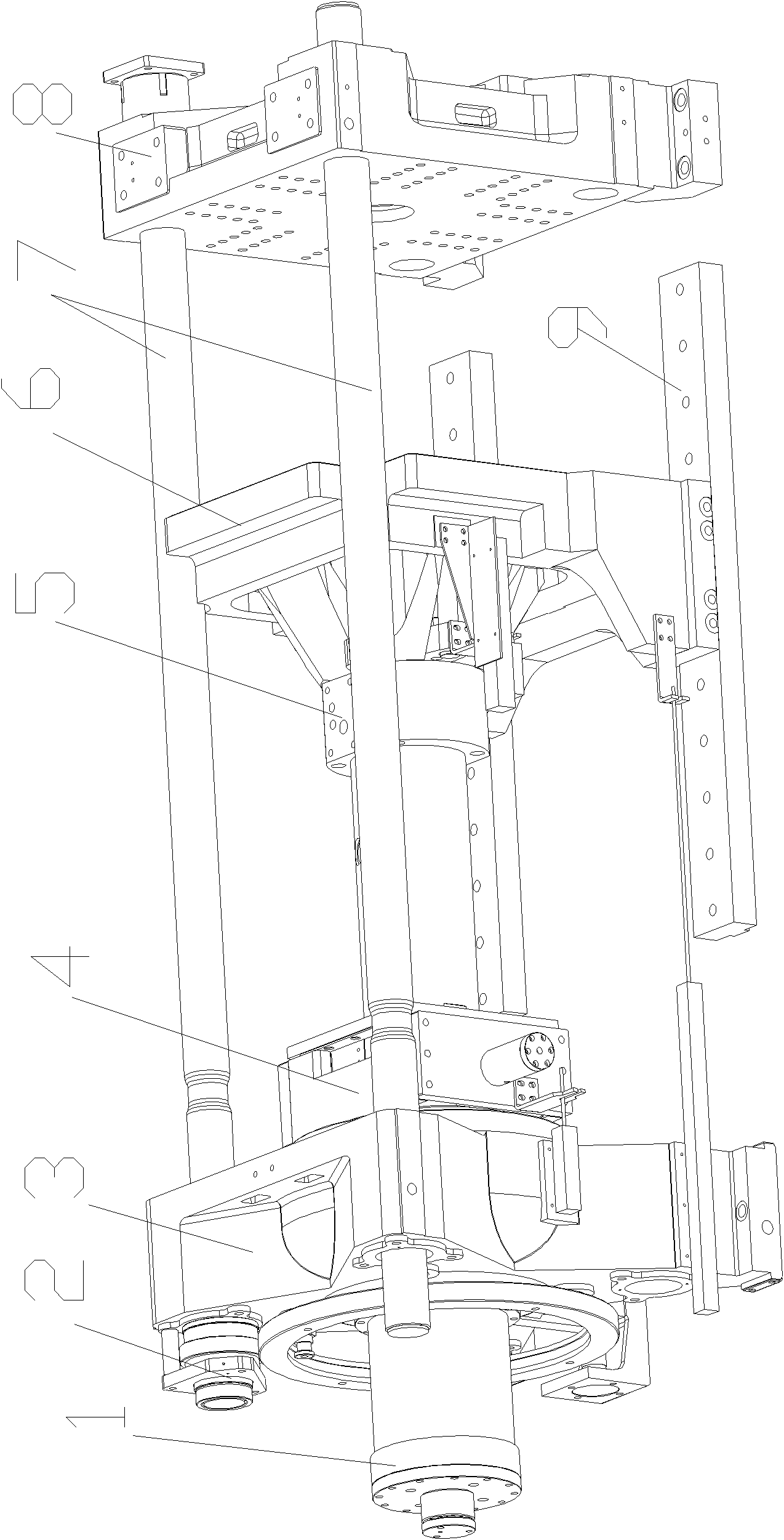
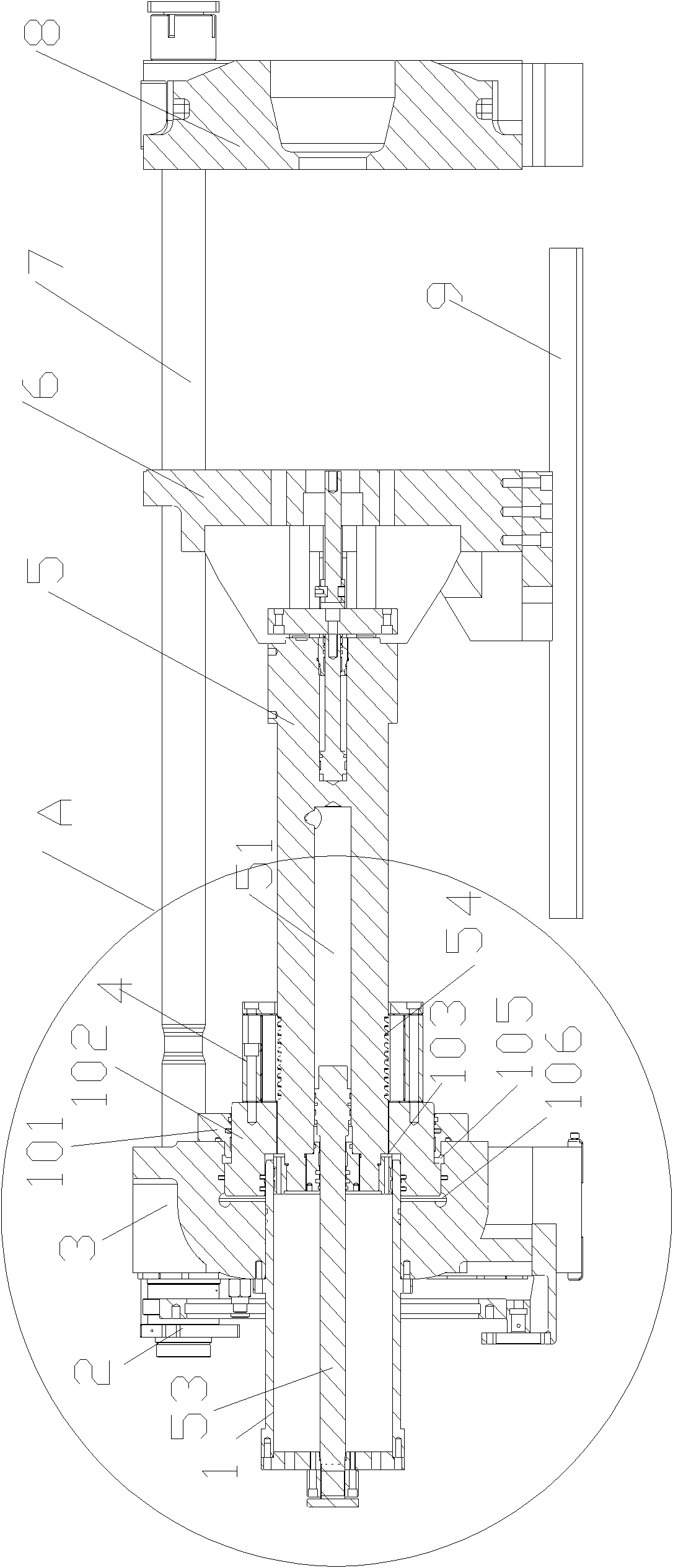
[0021] Such as figure 1 , figure 2 As shown, the composite direct pressure mold clamping device is mainly composed of the following components: ejector column guide sleeve 1, mold adjustment device 2, tail plate 3, entanglement cylinder assembly 4, ejector column 5, second plate 6, tie rod 7, Head plate 8, support plate linear guide 9.

[0022] The above-mentioned two boards 6 are arranged on the linear guide rail 9 and are guided by the linear guide rail 9 .

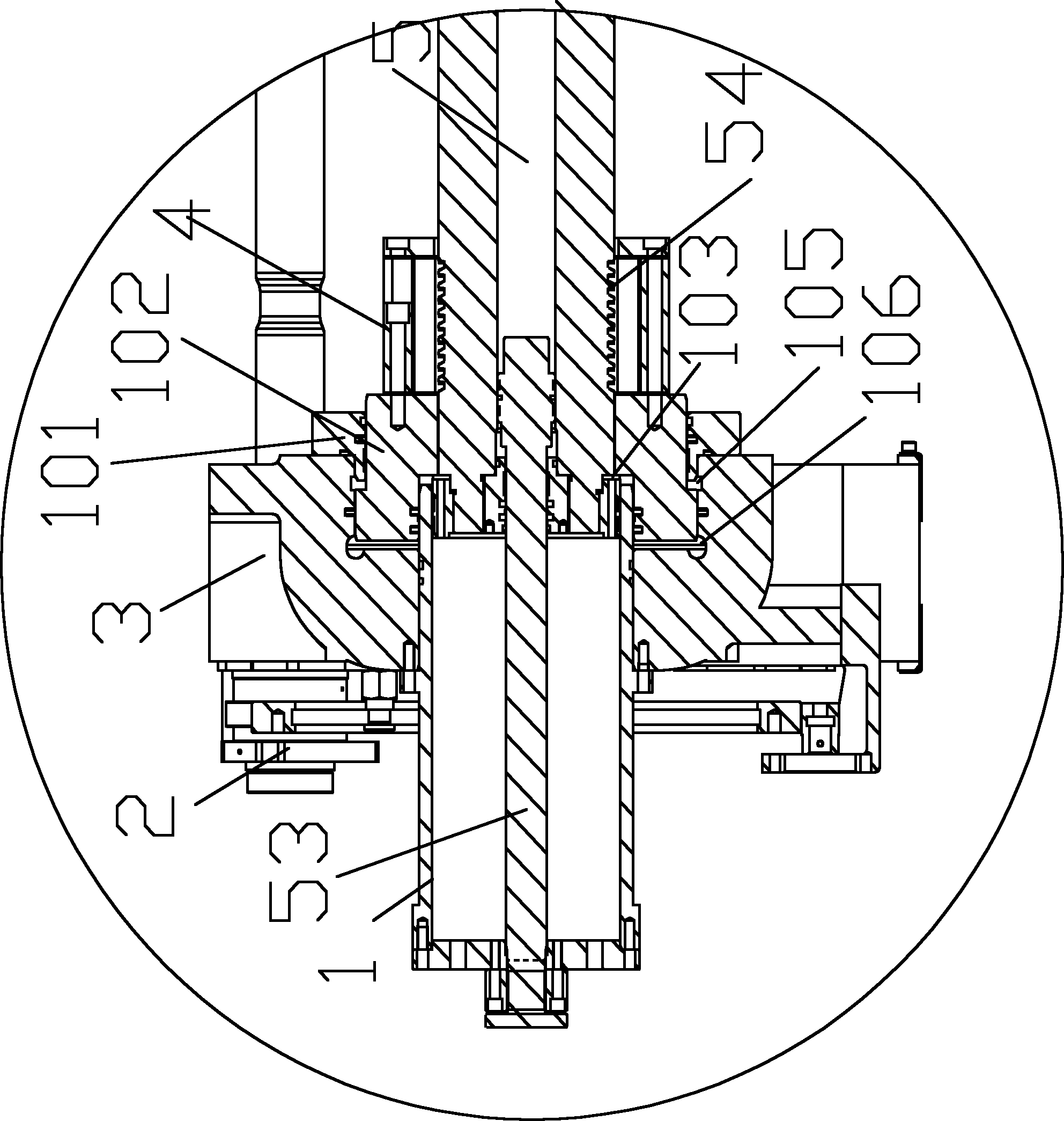
[0023] The jack post guide sleeve 1 penetrates vertically and is fixed at the central position of the tail plate 3 .

[0024] One end of the above-mentioned ejector column 5 is fixed on the second plate 6, and the other end passes through the clamping piston 102 and placed in the ejector column guide sleeve 1, the ejector column 5 can move in the ejector column guide sleeve 1, and t...


PUM


Abstract

The invention discloses a composite vertical compression mould clamping device comprising a tail board, a second board, a pull rod, a head board and a mould clamping cylinder, wherein the head board is connected in front of the pull rod; the tail end of the pull rod is connected with the tail board; the second board is arranged on a guide rail but not sleeved on the pull rod and is also provided with a support pillar; one end of the support pillar is fixed on the second board, and the other end is arranged in a guide sleeve of the support pillar after passing through a mould clamping piston and is also provided with a support pillar inner cavity in which a piston rod is arranged; one side of the piston rod forms a rodless cavity together with the support pillar inner cavity, and the other side forms a rod cavity; the rod cavity and the rodless cavity are both connected with an external oil path; the mould clamping cylinder comprises a mould clamping piton sleeve and a mould clamping piston; the mould clamping piston sleeve is fixed on the tail board; a mould clamping cylinder mould breaking cavity is formed between the mould clamping piston and the tail board; and mould clamping cylinder mould protecting cavities are respectively formed between the mould clamping piston and the tail board and between the mould clamping piston and the support pillar guide sleeve. The invention has the advantages that the pull rod is well stressed and not easy to break off; the second board is flexible and convenient to move; and the whole mechanism has strong adaptability on a mould and good whole rigidity.

Description

technical field [0001] The invention relates to a clamping device of an injection molding machine. Background technique [0002] In the existing injection molding machine industry, the link type mold clamping device occupies the main position. Its structure is generally composed of the head mold, the second plate and the tail plate. The head mold and the second plate are opened and closed through the linkage mechanism. The defect is 1. For a machine with a certain tonnage, the mold opening stroke should not be too large due to structural restrictions. For some products with deep cavity, this kind of machine cannot meet the requirements of the product. 2. The connecting rod mechanism is relatively complicated. When the tonnage of the machine is relatively large, the length and weight of the machine are relatively large, which also increases the cost accordingly. [0003] In order to improve the above deficiencies, a two-plate fully hydraulic mold clamping mechanism for inje...

Claims


Application Information

Patent Timeline
Patent Type & Authority Applications(China)
IPC IPC(8): B29C45/68
Inventor 高世权刘镇江
Owner HAITIAN PLASTICS MACHINERY GRP
Why Eureka
Try Eureka