Heat treatment apparatus

A heat treatment device and hot air technology, which is applied in the maintenance of heat treatment furnaces, heat treatment equipment, and heating chambers, can solve the problems of reduced workpiece processing, reduced cleanliness inside the furnace body, and floating, and achieves cleanliness, simple structure, and uniformity heating effect

Inactive Publication Date: 2010-09-22
KOYO THERMO SYST CO LTD
View PDF6 Cites 6 Cited by
  • Summary
  • Abstract
  • Description
  • Claims
  • Application Information

AI Technical Summary

Problems solved by technology

[0005] In the above-mentioned technique of Japanese Patent Laid-Open Publication No. 11-118356, since the partition plate for changing the flow velocity of the hot air is arranged at an incline, the place where the workpiece is installed increases in the height direction, and as a result, the processing amount of the workpiece decreases.
[0006] In addition, in the technology of the above-mentioned Japanese Patent Laid-Open Publication No.

Method used


Image

  • Heat treatment apparatus
  • Heat treatment apparatus
  • Heat treatment apparatus

Examples


Embodiment Construction

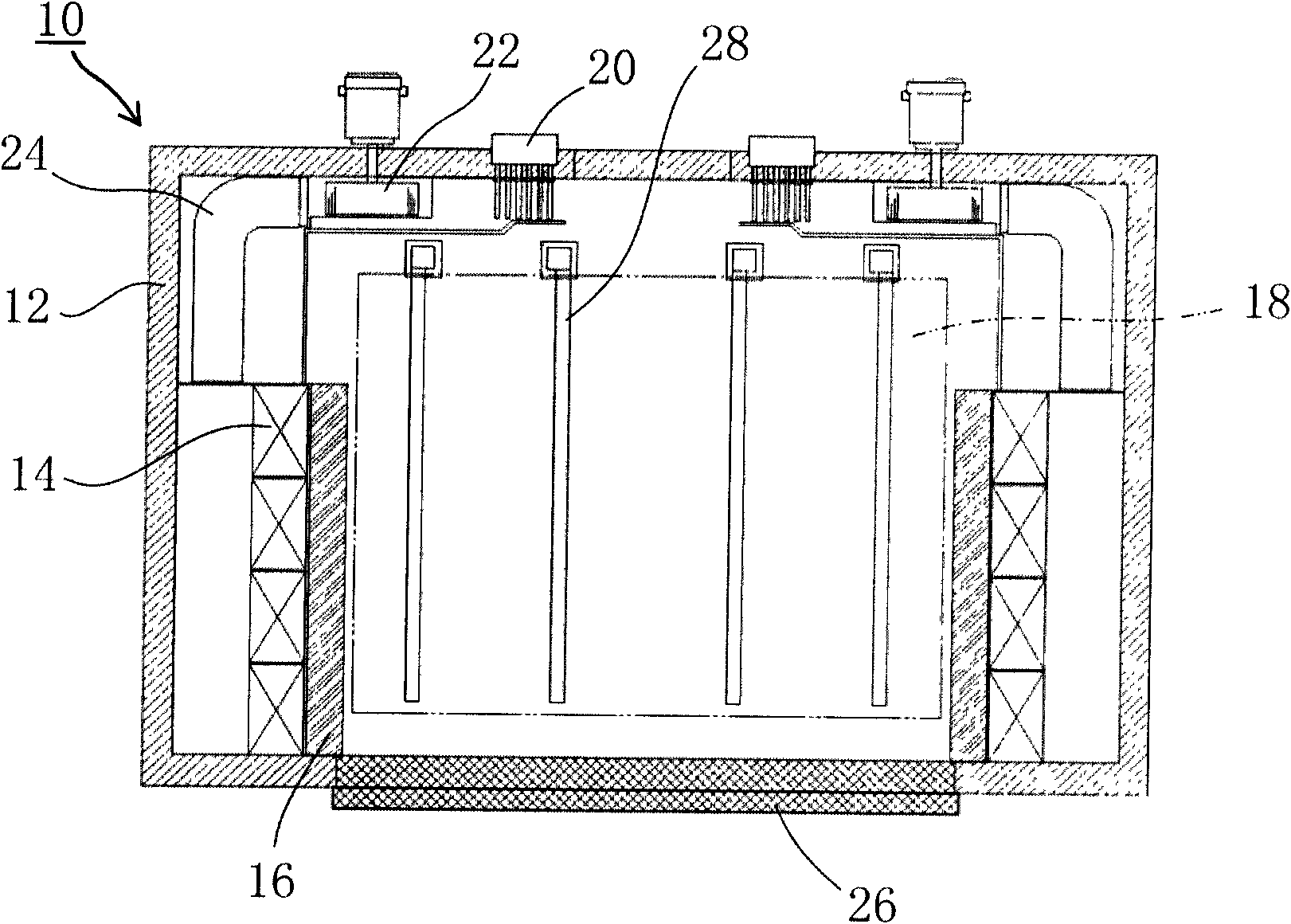
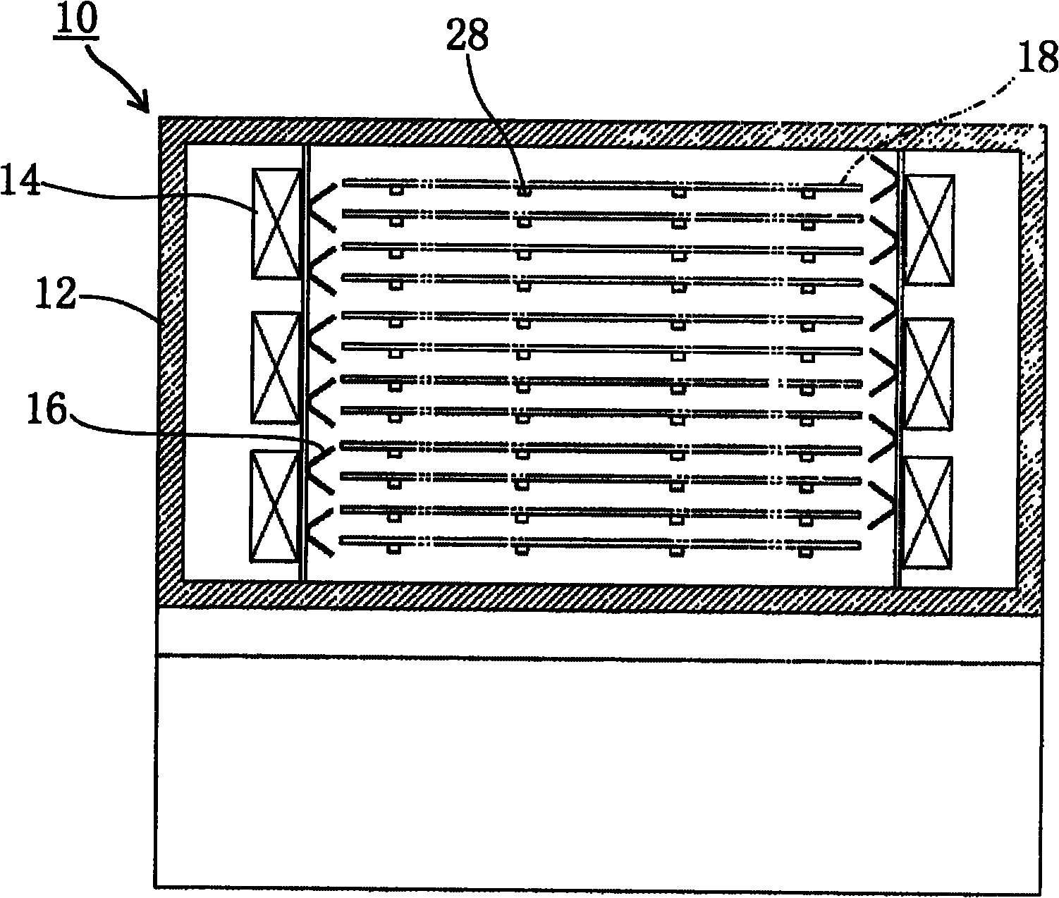
[0023] use Figure 1A and Figure 1B , the basic structure of the heat treatment apparatus 10 according to the embodiment of the present invention will be described. The heat treatment device 10 is a hot air circulation type clean oven, and uses circulating hot air to heat a flat plate-shaped workpiece 18 carried into the furnace body 12 .

[0024] A plurality of frame members 28 are provided inside the furnace body 12, and the frame members 28 support the workpiece 18 in multiple layers. A door 26 is provided on the front of the furnace body 12, and the door 26 is opened or closed when loading and unloading workpieces. The door 26 is composed of a plurality of shutters arranged in the vertical direction, and only the shutters corresponding to the floors assigned to the workpieces 18 to be carried in or carried out can be opened or closed.

[0025] A plurality of heaters 20 , a plurality of circulation fans 22 and a plurality of air ducts 24 are provided on the rear side of...


PUM


Abstract

A heat treatment device (10) of the invention comprises a furnace body (12), circulation fans (22), heaters (20), heat-resistant filters (14) and hot wind rectification plates (16). The hot wind rectification plates (16) are configured between the heat-resistant filters (14) and a workpiece (18). The hot wind rectification plates (16) cause the amount of the hot wind provided from one side of a first side surface above the workpice (18) to the workpice to be larger than that of the hot wind provided from one side of a second side surface to the workpiece. and on the other hand, causes the amount of the hot wind provided from one side of the second side surface below the same workpiece (18) to be larger than that of the hot wind provided from one side of the first side surface to the workpiece (18).

Description

technical field [0001] The invention relates to a heat treatment device which uses circulating hot air to heat workpieces. Background technique [0002] A heat treatment apparatus for heat-treating a workpiece includes a heating device of a hot air circulation system that heats the workpiece using hot air circulating inside a furnace body. In such a heat treatment apparatus of the hot air circulation system, there may be disadvantageous situations in which the temperature distribution of the upper wind and the lower wind of the workpiece is uneven, and the temperature of the lower wind of the workpiece is lowered. The larger the workpiece, the more serious this unfavorable situation has been, and various countermeasures have been taken in the past. [0003] For example, conventionally, there is a technique in which, when forced convection heating is performed on a flat workpiece, the spacer is arranged at an inclination so that the space between the leeward side and the spa...

Claims


Application Information

Patent Timeline
IPC IPC(8): C21D9/00F27B5/14
CPCF27B5/06F27B5/14F27D7/04F27D2007/045F27D2099/0086
Inventor 长嶋靖
Owner KOYO THERMO SYST CO LTD
Why Eureka
Try Eureka