High efficiency generator

A generator, high-efficiency technology, applied in the direction of electric components, electrical components, electromechanical devices, etc., can solve the problem that the power generation efficiency of the generator needs to be improved, and achieve the effect of simplifying the structure, improving the efficiency, and improving the power generation efficiency

Inactive Publication Date: 2010-09-22
石为民
View PDF5 Cites 3 Cited by
  • Summary
  • Abstract
  • Description
  • Claims
  • Application Information

AI Technical Summary

Problems solved by technology

[0007] However, the power generation efficiency of the generator still needs to be improved

Method used


Image

  • High efficiency generator
  • High efficiency generator
  • High efficiency generator

Examples


Embodiment Construction

[0028] The present invention will be further described in detail below through specific embodiments and in conjunction with the accompanying drawings.

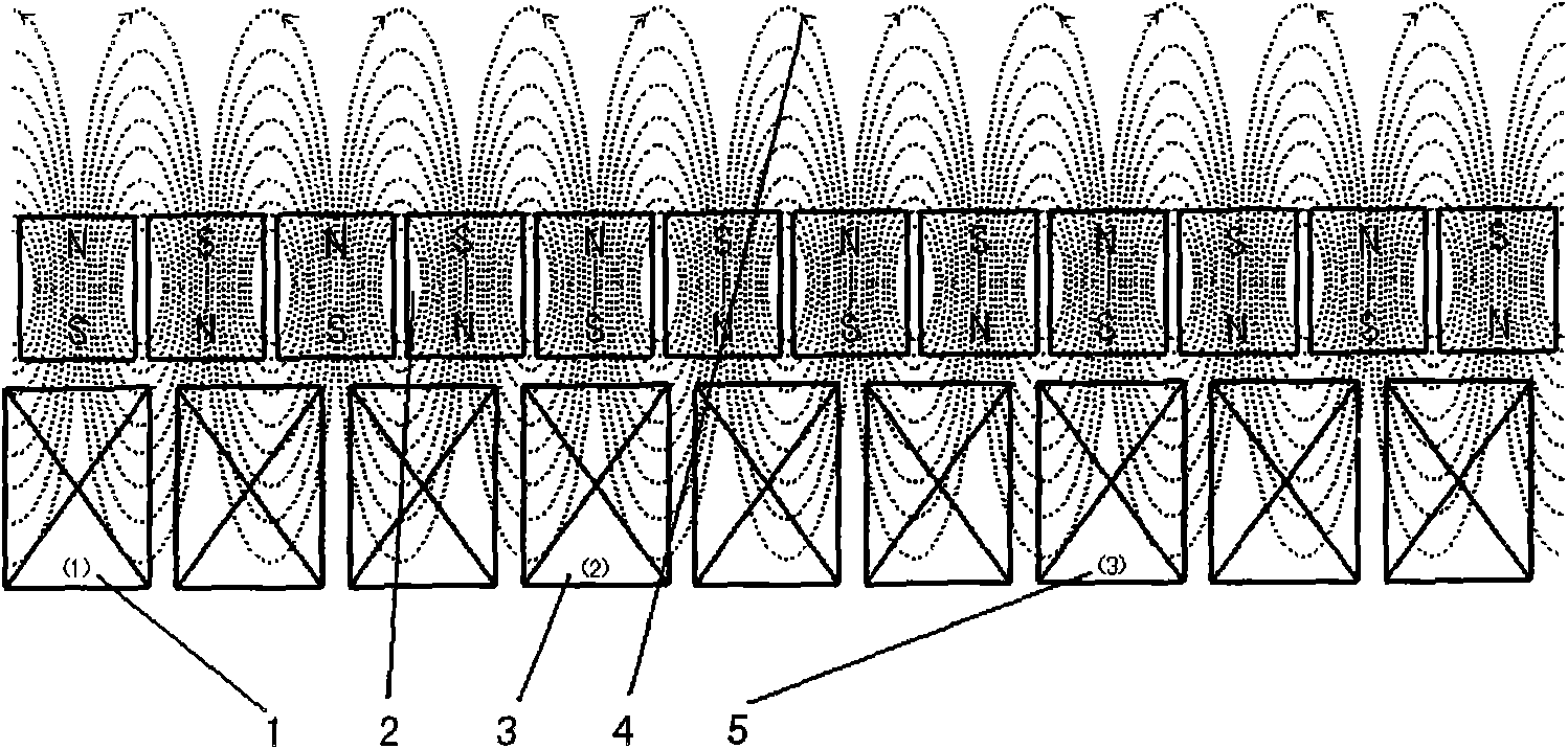
[0029] According to the basic principle "Lengz's law" of the electromotive force generated by the generator, the armature winding of the generator must be in a position orthogonal to the magnetic field, and the generated electromotive force is the strongest. Such as figure 1 As shown: 1, 3, and 5 in the figure are three tiled armature windings orthogonal to the magnetic field; 2 represents the tiled rotating magnetic field; 3 represents the radiation range and circulation direction of the magnetic force lines of the magnetic field.

[0030] It is not difficult to see from the figure that the armature winding offset from the magnetic field is a multiple of "N" of the armature winding orthogonal to the magnetic field. The electromotive force generated by the armature windings 1, 3, and 5 orthogonal to the magnetic field can onl...


PUM


Abstract

The invention discloses a high efficiency generator, which comprises a shell body, a main shaft rotatablely supported on a shell, a first stator arranged in a shell and provided with a plurality of armature coils, and a first rotor arranged on a main shaft and generating an alternating magnetic field. At least one extension stator is further arranged in the shell. The main shaft is provided with at least one extension rotor corresponding to the extension stator. The invention improves the efficiency of the electric generator by adding at least one stator rotor generating unit.

Description

technical field [0001] The invention relates to a generator, in particular to a generator which can fully improve power generation efficiency. Background technique [0002] In the field of traditional generators, since the generator was born, the electromechanical conversion efficiency of the generator has always been very low. The average efficiency of thermal power generation in the world is only 31%. [0003] As far as three-phase generators are concerned, the number of stator and rotor poles is usually a common multiple of three. At each static working point of the generator, only three coil windings facing the rotating magnetic field will generate positive electromotive force. The wire wrap adjacent to the wire wrap not only cannot generate positive electromotive force, but also the opposite electromotive force will be generated by the wire wrap winding receiving the opposite magnetic field polarity. The three wire wrap windings that generate positive electromotive f...

Claims


Application Information

Patent Timeline
Patent Type & Authority Applications(China)
IPC IPC(8): H02K16/00H02K1/27H02K1/16H02K3/00
Inventor 石为民
Owner 石为民
Why Eureka
Try Eureka