Positioning compaction device, compaction device and tool for auxiliary machining of chassis of motor train

A pressing device and auxiliary processing technology, applied in the direction of positioning device, workpiece clamping device, metal processing equipment, etc., can solve the problems of large volume, poor adjustability, inconvenient handling and movement, etc.

Active Publication Date: 2010-09-29
CRRC TANGSHAN CO LTD
View PDF6 Cites 55 Cited by
  • Summary
  • Abstract
  • Description
  • Claims
  • Application Information

AI Technical Summary

Problems solved by technology

[0003] The present invention provides a positioning and pressing device, a pressing device and tooling for assisting in the processing of the underframe of the motor car, to solve the problem of the tooling of the underframe of the mo

Method used


Image

  • Positioning compaction device, compaction device and tool for auxiliary machining of chassis of motor train
  • Positioning compaction device, compaction device and tool for auxiliary machining of chassis of motor train
  • Positioning compaction device, compaction device and tool for auxiliary machining of chassis of motor train

Examples


Embodiment 1

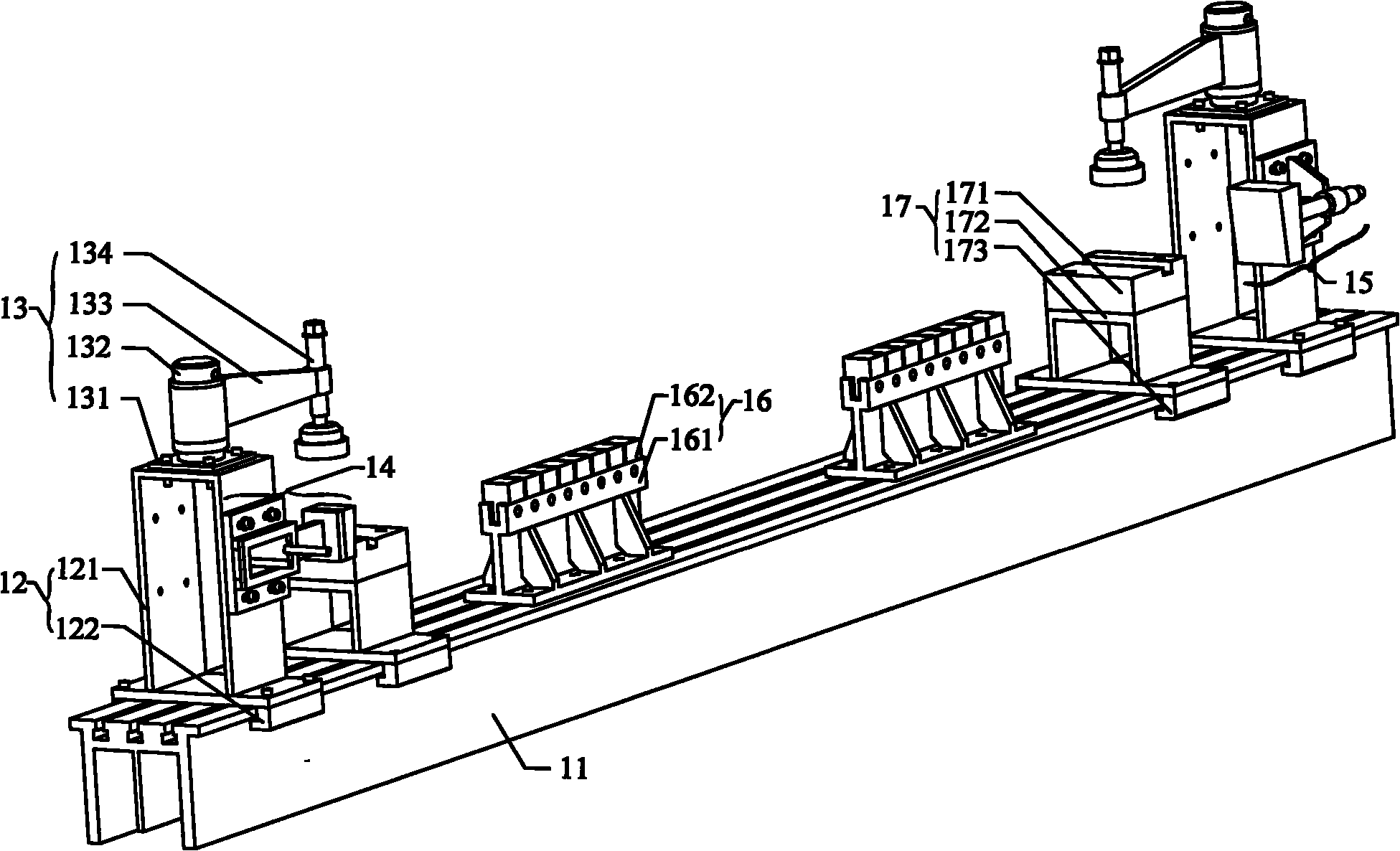
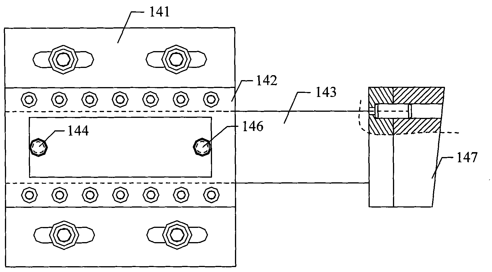
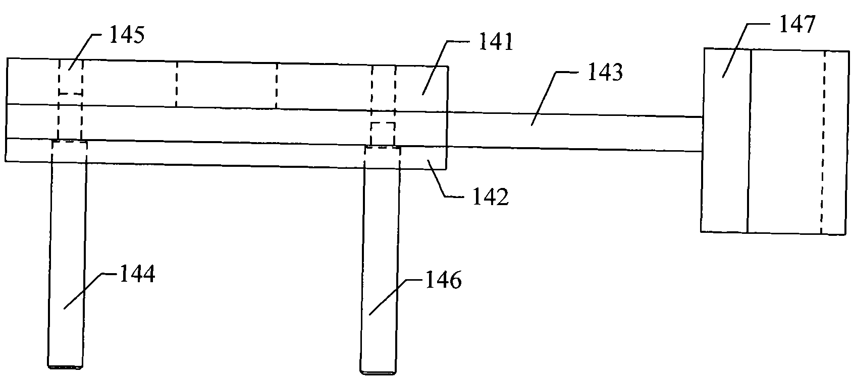
[0035] figure 1 It is a perspective view of the positioning and pressing device for auxiliary processing of the underframe of the motor car according to the present invention. figure 2 It is a front view of the side positioning structure of the positioning and pressing device of the present invention. image 3 It is a top view of the side positioning structure of the positioning and pressing device of the present invention. Figure 4 It is a front view of the lateral pressing structure in the positioning and pressing device of the present invention. Figure 5 It is a top view of the lateral pressing structure in the positioning and pressing device of the present invention. Image 6 It is a front view of the adjustable intermediate support structure in the positioning and pressing device of the present invention. Figure 7 It is a side view of the adjustable intermediate support structure in the positioning and pressing device of the present invention. Figure 8 It is a top view of...

Embodiment 2

[0046] Figure 15 It is a three-dimensional view of the pressing device for auxiliary processing of the underframe of the motor car according to the present invention. Combine Figure 1 to Figure 15 As shown, the pressing device of this embodiment differs from the positioning and pressing device of the first embodiment only in that there is no side positioning structure 14 and lateral pressing structure 15, and the rest of the structure is the same as that of the positioning and pressing device, which will not be repeated here. .

Embodiment 3

[0048] Further, the tooling for auxiliary processing of the underframe of the motor car in this embodiment includes a plurality of positioning and pressing devices of the first embodiment; or, a plurality of positioning and pressing devices of the first embodiment and a plurality of pressings of the second embodiment. The tightening device, in addition, the tooling can be provided with at least one positioning and pressing device corresponding to the two ends of the motor car underframe.

[0049] specifically, Figure 16 It is a schematic diagram of the tooling used for auxiliary processing of the underframe of the electric vehicle to clamp the underframe of the electric vehicle. Such as Figure 16 As shown, the tooling for auxiliary processing of the motor car underframe in this embodiment includes three positioning and pressing devices 21 in the first embodiment above and eight pressing devices 22 in the second embodiment above to perform the processing of the underframe of the ...


PUM


Abstract

The invention provides a positioning compaction device, a compaction device and a tool for the auxiliary machining of chassis of motor trains. The positioning compaction device comprises a beam, two support frames, two rotary vertical compaction structures, a side positioning structure, a lateral butting structure and two adjustable intermediate support structures, wherein the two support frames are slidably arranged on both sides of the upper surface of the beam respectively; the two rotary vertical compaction structures are arranged on the tops of the two support frames respectively; the side positioning structure is arranged on the lateral part of one support frame in the two support frames; the lateral butting structure is arranged on the lateral part of the other support frame in thetwo support frames; and the two adjustable intermediate support structures are arranged on the upper surface of the beam and are positioned between the two support frames. The positioning compaction device realizes the modular design of the tool for the auxiliary machining of the chassis of the motor trains and solves the technical problems of large volume and inconvenient carrying and movement of a tool structure for the auxiliary machining of the chassis of the motor trains and incapability of auxiliary machining of the chassis of the motor trains with different types due to low adjustability.

Description

Technical field [0001] The invention relates to the field of tooling for processing motor cars, in particular to a positioning and pressing device, a pressing device and tooling used for auxiliary processing of a motor car underframe. Background technique [0002] The motor car underframe is an important component of the motor car, which is mainly processed with the aid of the motor car underframe tooling. At present, the underframe tooling used for auxiliary processing of the underframe of the electric vehicle has a large structure and is not convenient for handling and movement; in addition, its adjustability is poor and cannot meet the requirements for auxiliary processing of different types of underframes of the electric vehicle. Summary of the invention [0003] The present invention provides a positioning and pressing device, a pressing device and a tooling for auxiliary processing of the underframe of a motor car, which is used to solve the problem of the large size of the ...

Claims


Application Information

Patent Timeline
IPC IPC(8): B23Q3/00B25B11/00
CPCB23Q3/062B23Q1/037B25B5/10B23Q3/069
Inventor 刘军
Owner CRRC TANGSHAN CO LTD
Why Eureka
Try Eureka