Disc brake

A technology of disc brakes and pads, applied in the direction of brake types, axial brakes, brake components, etc., can solve problems such as easy lowering, unstable shape, easy permanent deformation, etc., to reduce drag and vibration, prevent Sloshing, achieving a stabilizing effect

Inactive Publication Date: 2010-09-29
AKEBONO BRAKE IND CO LTD
View PDF9 Cites 3 Cited by
  • Summary
  • Abstract
  • Description
  • Claims
  • Application Information

AI Technical Summary

Problems solved by technology

Therefore, the respective pad clips 14a, 14b are easily permanently deformed, and it becomes easy to reduce the force (restraining force) pressing the inner and outer pads 5, 6 by the respective pad clips 14a, 14b. On the one hand, there is also the possibility that the shape of each pad 5, 6 becomes unstable.
In addition, as described above, since the direction of the applied moment changes during forward rotation and reverse rotation, for example, when the brake is started, the engaging portions on the front side in the rotation direction of the rotor 1 abut (collide) against each other, thereby May be prone to noise based on the abutment (collision)

Method used


Image

  • Disc brake
  • Disc brake
  • Disc brake

Examples


Embodiment Construction

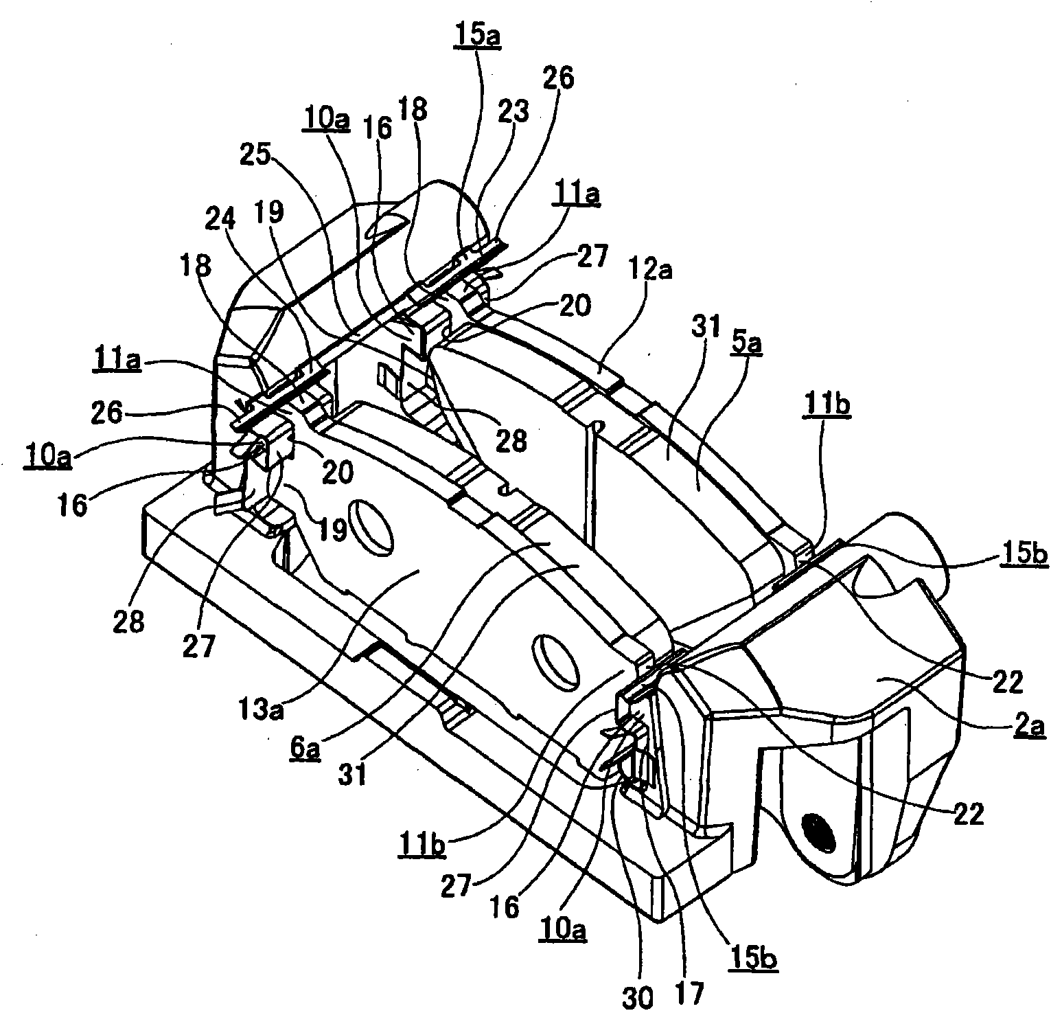
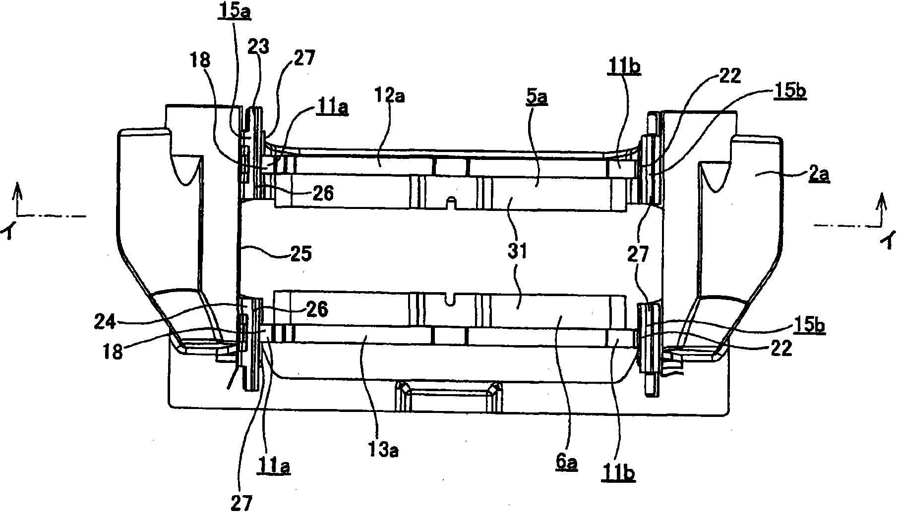
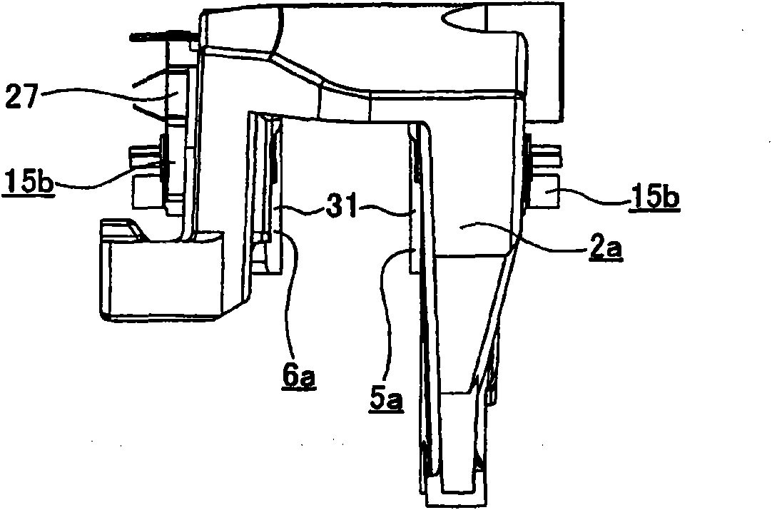
[0074] Figure 1~6 An example of the embodiment of the present invention is shown. In addition, this example is characterized in that in order to stabilize the shape of the inner and outer pads 5a, 6a, and to reduce the pull and vibration (noise, chatter) of each pad 5a, 6a, each The structure of the portion where the pads 5a, 6a are supported by the bracket 2a, the structure of the pad clips 15a, 15b, etc. have been improved. Regarding the structure and function of other parts, for example because of the Figure 7-11 The shown conventional structures are the same, so illustrations and descriptions related to the same parts are omitted or simplified, and the characteristic parts of this example will be mainly described below.

[0075] In the case of this example, the rotor 1 (refer to Figure 7-9 ) on both sides of the rotor 1 in the circumferential direction, are respectively formed with holder-side engaging portions 10a, 10a. In addition, pad-side engaging portions 11a, 1...


PUM


Abstract

The invention provides a disc brake which realizes a structure capable of achieving the sharp stabilization for the inward and outward pads (5a), and reducing pulling and vibration (noise, tremble) for the pads (5a). Among abutment parts of pad-side engagement parts (11a, 11b) and support-member-side engagement parts (10a, 10a), a portion (Af) which bears a tangential force (Ff) applied to the pad (5a, 6a) during a forward rotation of the rotor on a forward side of the forward rotation of the rotor is positioned inwardly in a radial direction of a rotor with respect to a virtual tangent (k) at a centroid (O) of the pad (5a, 6a) of a virtual circle having a center identical with a center of the rotor and passing through said centroid (O). Among the abutment parts, portions (Bf, Cf) which bear a rotational moment (Mf) applied to the pad (5a, 6a) during the forward rotation of the rotor are positioned at the circumferential both end parts of a support member (2a) and outwardly in the radial direction of the rotor with respect to the virtual tangent (k).

Description

technical field [0001] The present invention relates to an improvement of a disc brake used for braking an automobile. Specifically, in a floating caliper type disc brake, it is intended to realize a structure capable of stabilizing the form of the pad and reducing drag and vibration (noise, chatter) of the pad. Background technique [0002] Conventionally, as a disc brake for performing braking of a vehicle such as an automobile, for example, for a bracket, a caliper is supported so as to be freely displaceable in the axial direction, and in the caliper, an air cylinder is provided only on one side with respect to a rotor Floating caliper type disc brakes with parts and pistons are widely known from the descriptions in Patent Documents 1 to 3, and are actually widely used. Figure 7-9 A floating caliper type disc brake described in Patent Document 2 among them is shown. [0003] With regard to this disc brake, through a pair of guide pins 4, 4, the axial direction of the r...

Claims


Application Information

Patent Timeline
Patent Type & Authority Applications(China)
IPC IPC(8): F16D55/225F16D65/095
CPCF16D65/0972F16D2055/0008F16D65/095F16D65/0977F16D55/224
Inventor 前原利史
Owner AKEBONO BRAKE IND CO LTD
Why Eureka
Try Eureka