Driving force transmitting device and vehicle seat slide device

A transmission device and driving force technology, applied in vehicle seats, transmission devices, gear transmission devices, etc., can solve the problems of difficult assembly and assembly work of the driving force transmission device, and achieve fast transportation and storage processing, transportation and storage. Handling easy effects

Inactive Publication Date: 2010-09-29
AISIN SEIKI KK
View PDF5 Cites 9 Cited by
  • Summary
  • Abstract
  • Description
  • Claims
  • Application Information

AI Technical Summary

Problems solved by technology

Assembly work becomes more difficult if the insertion position on the reduction section side (helical gear edge) deviates from the corresponding position to be inserted in the right/le

Method used


Image

  • Driving force transmitting device and vehicle seat slide device
  • Driving force transmitting device and vehicle seat slide device
  • Driving force transmitting device and vehicle seat slide device

Examples


Embodiment Construction

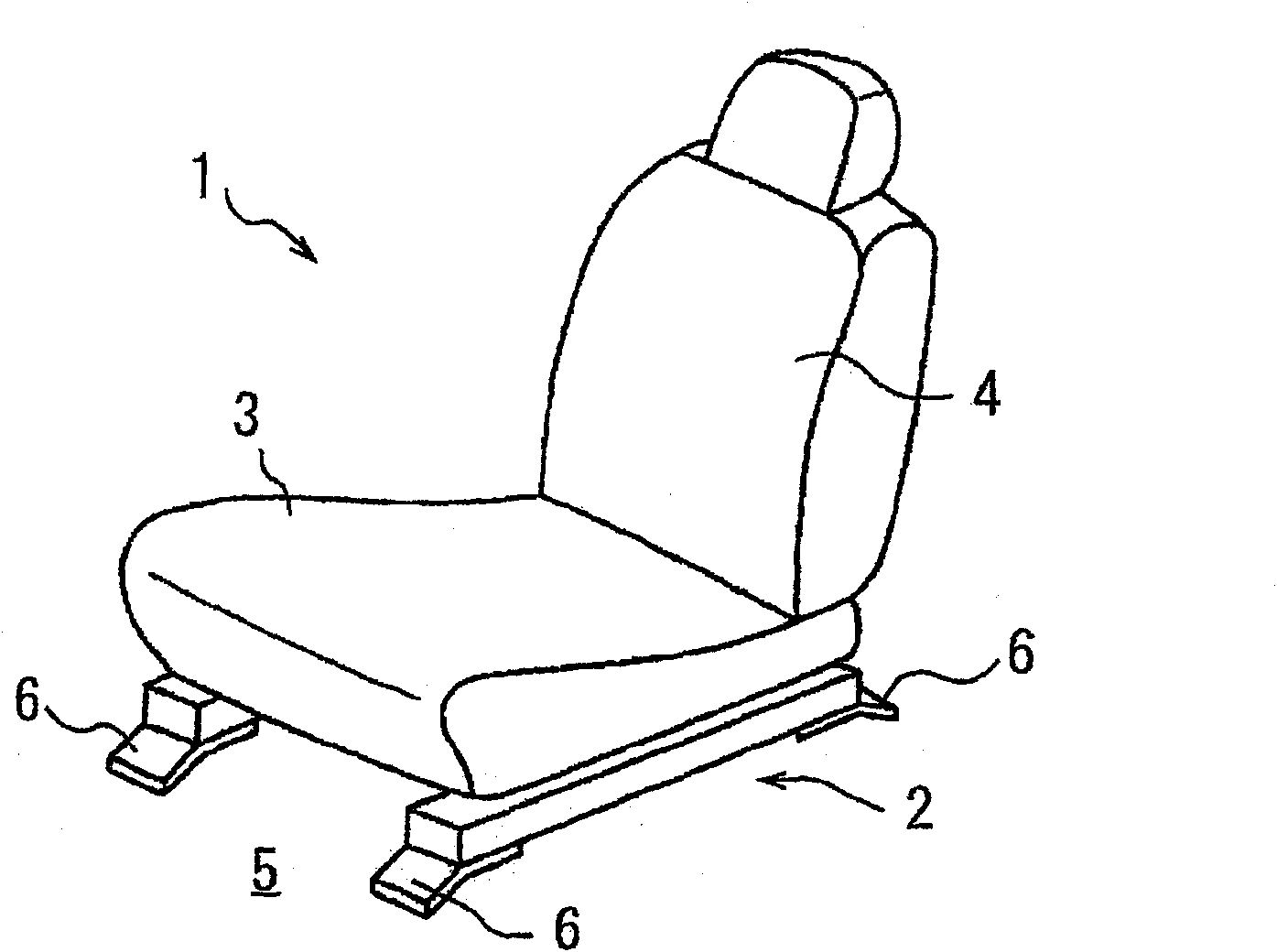
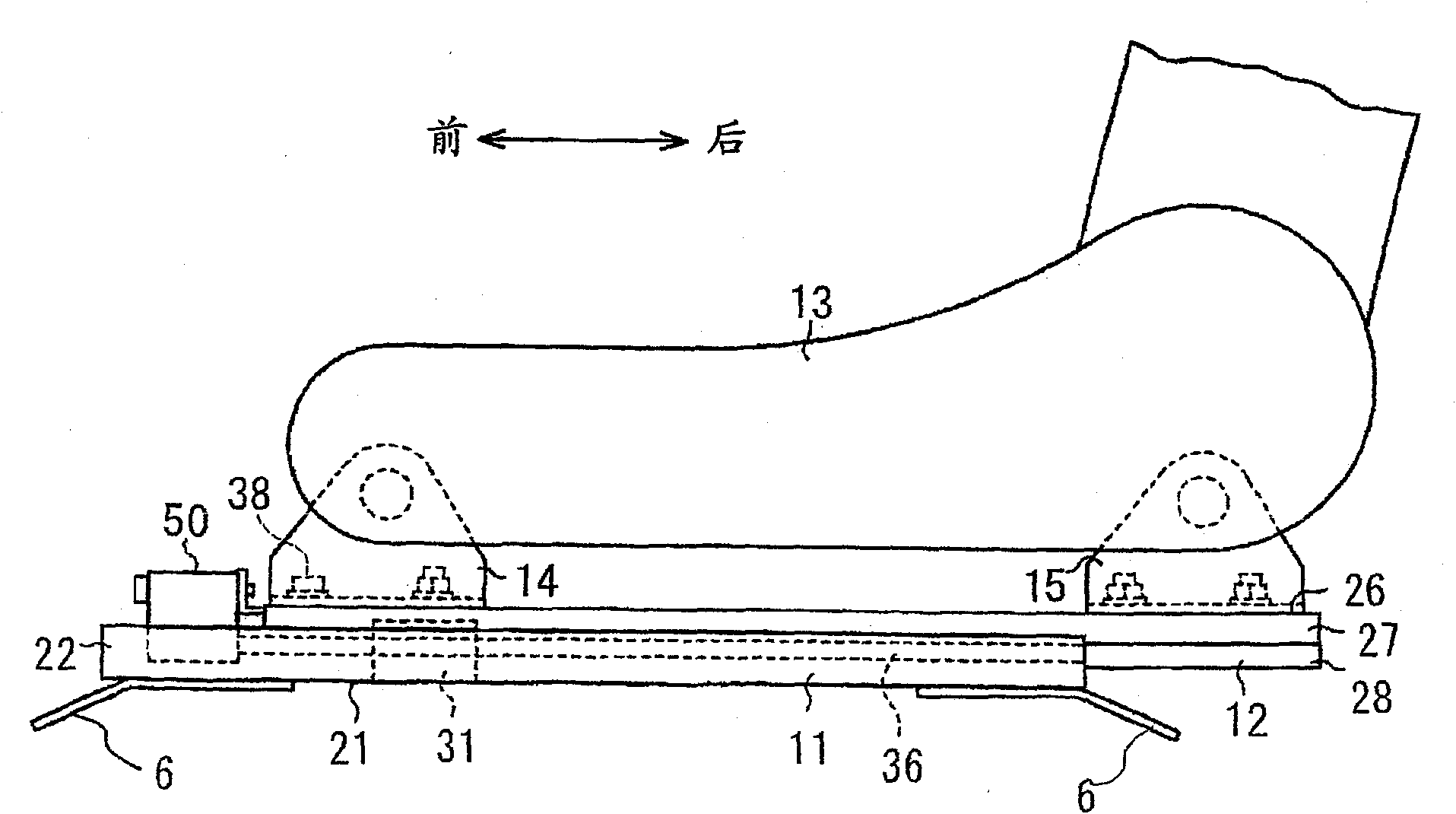
[0037] A driving force transmission device suitable for a vehicle seat sliding device will be described below with reference to the drawings. figure 1 is a perspective view of a seat 1 with a vehicle seat slide 2, figure 2 is a side view of the vehicle seat sliding device 2 . It should be understood that the terms "right and left", "front and rear", "widthwise and axial direction", and "upper and lower" refer to directions or positions relative to the vehicle.

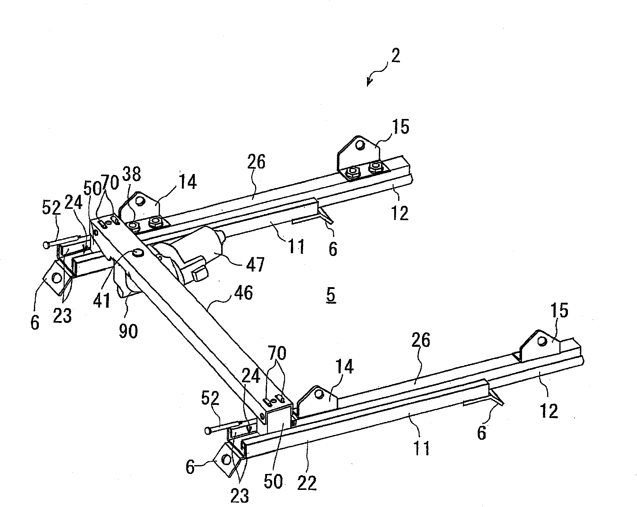
[0038] Such as figure 1 The illustrated seat 1 includes: a seat cushion 3 supported by a vehicle seat slide device 2 and capable of sliding in the front / rear direction relative to a vehicle floor 5; and a seat back 4 supported at a rear end portion of the seat cushion 3 . The vehicle seat sliding device 2 is as figure 2 and 3 The power seat type is shown, and the power seat sliding device 2 includes a pair of lower rails 11, a pair of upper rails 12, a screw shaft 36 as a drive shaft, a nut member 31 (not shown)...


PUM


Abstract

The invention relates to a driving force transmitting device and a vehicle seat slide device. A driving force transmitting device having a direction changing gear mechanism which transmits a rotation torque from a drive shaft (48) to a driven shaft (36) having an axis extending in a direction different from a direction of an axis of the drive shaft (48). The direction changing gear mechanism (50) includes an input gear (67) attached to the drive shaft (48) for restricting a relative rotation and engaged with an output gear (66), a gear housing (53) rotatably supporting the output gear (66) and the input gear (67) under engagement condition, wherein one of the output gear and the input gear is provided with a rotation phase adjusting portion (66d) exposed outside for adjusting a rotation phase of the output gear (66) relative to a rotation phase of the second engagement portion of the driven shaft (36) upon the output gear (66) being assembled to the driven shaft (36).

Description

technical field [0001] The present disclosure relates to a driving force transmission device and a vehicle seat sliding device to which the driving force transmission device is applied. Background technique [0002] For known vehicle power seats, various driving force transmission devices have been proposed which transmit the torque of a drive shaft rotated by a drive source such as a motor to a driven shaft whose axis is aligned with the The axis of the drive shaft extends in different directions. In these devices, torque is transmitted by engaging a worm gear of a drive shaft with a helical gear of a driven shaft. The worm gear and the helical gear are rotatably accommodated in the supporting member (gearbox). Such a driving force transmission device is shown in Patent Document 1, wherein the driving force transmission device for transmitting the torque of the drive shaft to the screw shaft includes a worm gear provided at the drive shaft, a a helical gear and a gear ho...

Claims


Application Information

Patent Timeline
IPC IPC(8): F16H1/18F16H57/02F16H21/10B60N2/02B60N2/06F16H55/17
CPCB60N2/067B60N2/0232Y10T74/1966B60N2/02246
Inventor 古贺义孝铃村宏和清水寿得
Owner AISIN SEIKI KK
Why Eureka
Try Eureka