Vehicle headlamp

A technology for headlights and vehicles, applied in vehicle lighting systems, headlights, vehicle parts, etc., can solve the problems of reduced machinability, inconsistent appearance, increased manufacturing costs, etc., and achieves good integrity and improved light efficiency. Effect

Inactive Publication Date: 2010-09-29
TOYODA GOSEI CO LTD
View PDF7 Cites 10 Cited by
  • Summary
  • Abstract
  • Description
  • Claims
  • Application Information

AI Technical Summary

Problems solved by technology

However, in the case of this replacement, since no shielding member is provided in the reflective light source unit, the light source member will be seen from the outside in the configuration of JP-A-2006-302711
If the light source unit is concealed with a cover as described in JP-A-2007-059075, the a

Method used


Image

  • Vehicle headlamp
  • Vehicle headlamp
  • Vehicle headlamp

Examples


Embodiment Construction

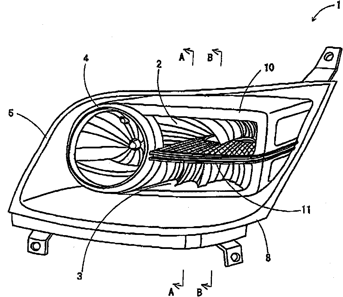
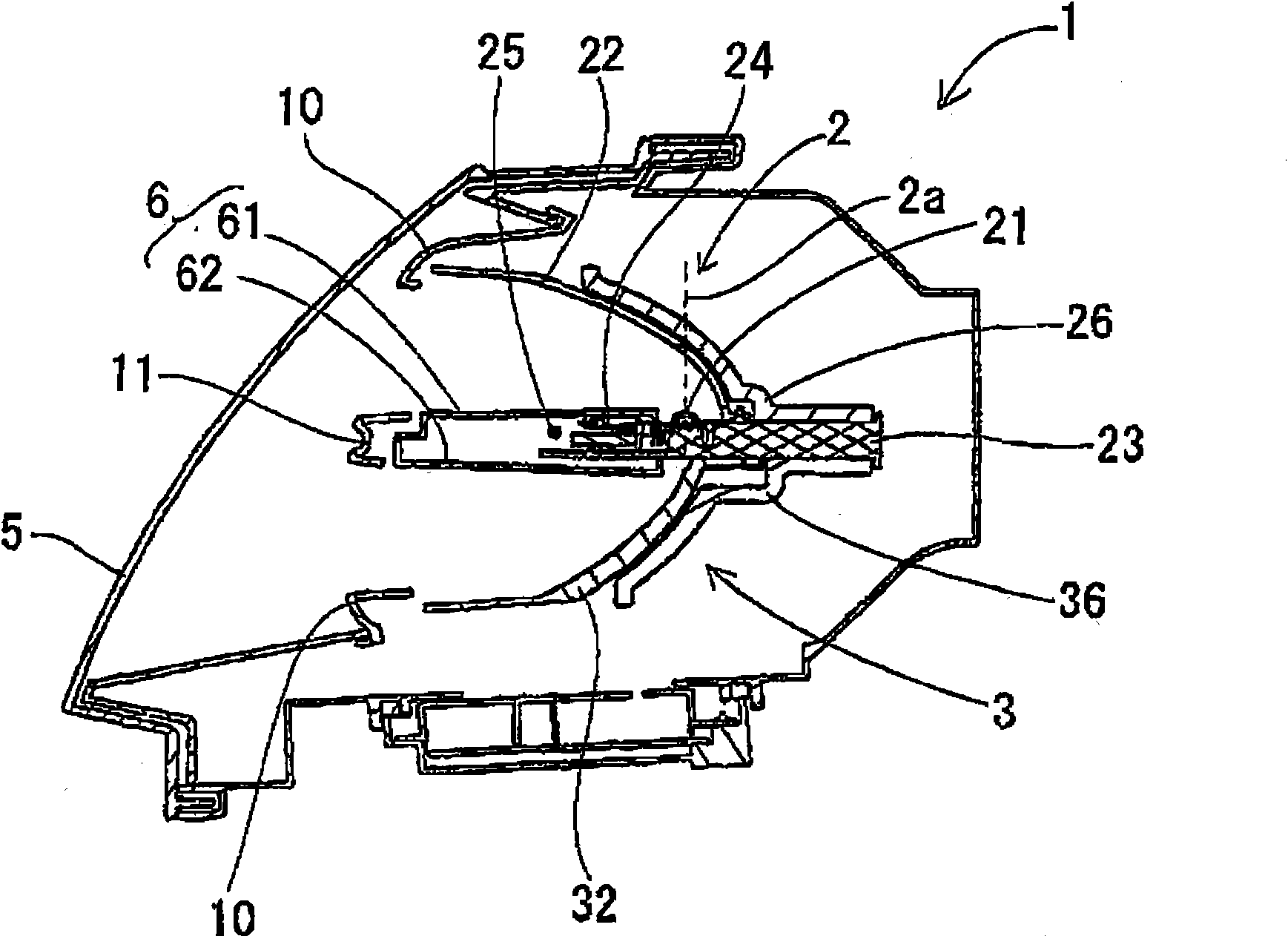
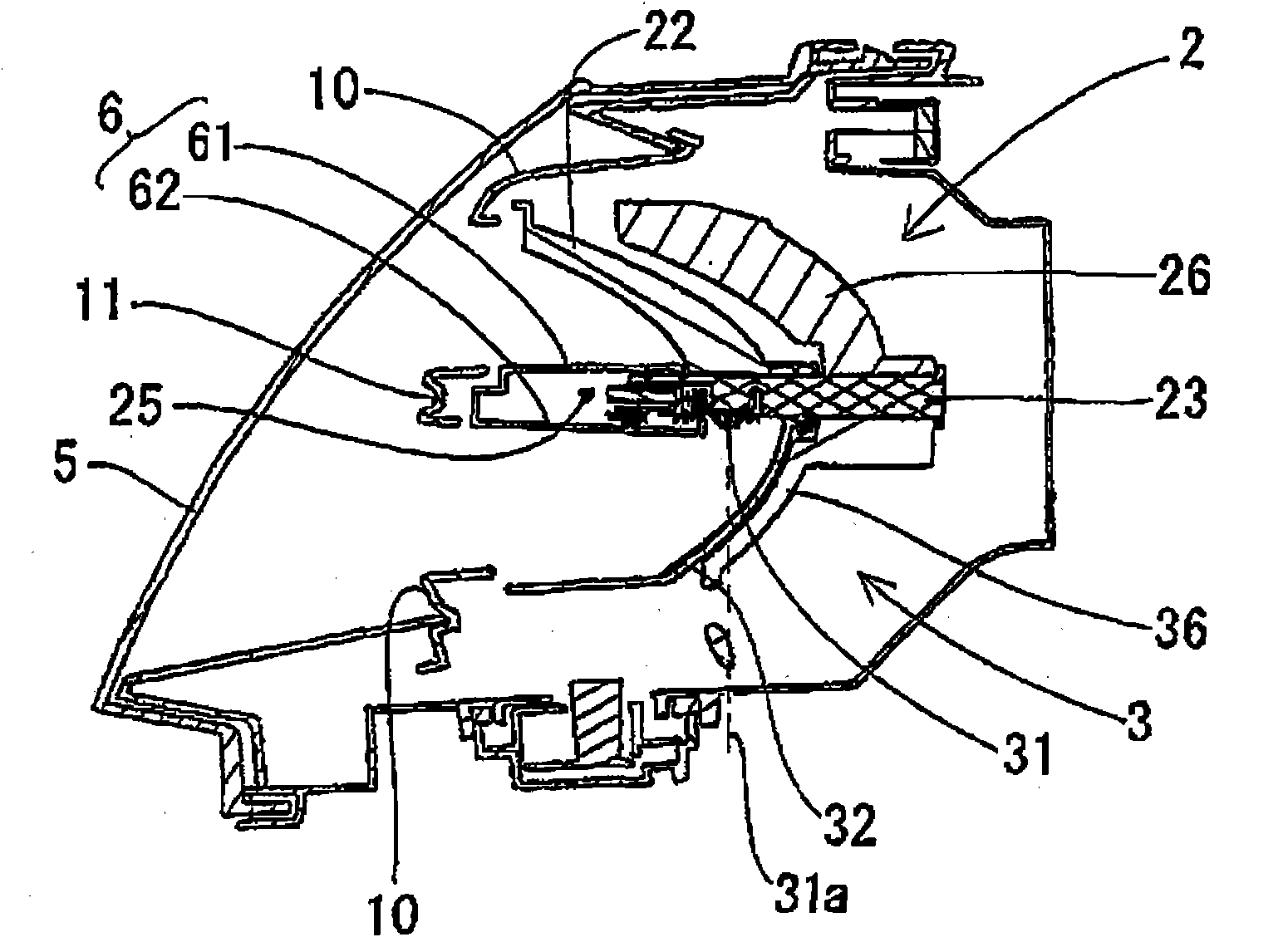
[0014] A vehicle headlamp according to an exemplary embodiment of the present invention is provided with a first low beam member and a second low beam member. The first low beam member and the second low beam member are respectively constituted by reflective light source units. The reflective light source unit is provided with a light source and a reflector, and outputs light by reflecting light emitted by the light source in a predetermined direction with the reflector. As a light source unit different from the reflection type light source unit, there is a projection type light source unit. In addition to the light source and the reflector, the projection light source unit is also provided with a projection lens and a shield. Since the reflection type light source unit does not use a projection lens, the light dissipation of the reflection type light source unit is smaller than that of the projection type light source unit. Therefore, if a reflective light source unit is us...


PUM


Abstract

A vehicle head lamp comprising a first low beam member including a first light source part; a second low beam member including a second light source part, wherein the first low beam member and the second low beam member are arranged in a vertical direction and are both reflective type; a first frame including a partition, the first frame supporting the first low beam member and the second low beam member, and the partition separating the first low beam member and the second low beam member; and a storage arranged in a rear side of the partition, the storage accommodating the first and the second light source parts.

Description

[0001] Cross-References to Related Applications [0002] This application claims priority from Japanese Patent Application No. 2009-072605 filed on Mar. 24, 2009, and the subject matter of that application is hereby incorporated by reference. technical field [0003] This invention relates to improvements in vehicle headlamps. Background technique [0004] There are vehicle headlamps provided with a plurality of light source units. JP-A-2006-302711 and JP-A-2007-324042 disclose related car lights, the car lights are provided with a projective light source unit and a reflective light source unit, and the projective light source unit and reflective light source unit are along the Arranged vertically. In the configuration of JP-A-2006-302711, improvement in positioning accuracy is achieved by integrally forming a plurality of reflective surfaces and a decorative member in a projection-type light source unit. In addition, the light source parts are prevented from being seen f...

Claims


Application Information

Patent Timeline
IPC IPC(8): F21S8/10F21V19/00B60Q1/04F21W101/10
CPCF21V29/246B60Q1/0041F21S48/1159F21S48/328F21V29/2237F21V29/004F21V29/70F21V29/777F21V29/89F21S41/148F21S41/19F21S45/47
Inventor 田中义治三沢明弘荒川哲也
Owner TOYODA GOSEI CO LTD
Why Eureka
Try Eureka